24
ARMSPROCEDURE 2
A
R
M
S
"T" ARM INSTALLATION (FIGURE 6)
1. Remove the large wheels from the wheelchair.
2. Turn the wheelchair frame over so that the cast-
ers are pointing up.
3. Slide two (2) coved washers over the mounting
bolts of the arm socket. Make sure they sit flush
against the arm socket.
4. Install the arm socket with coved washers into
the mounting holes on the wheelchair frame
making sure the larger half of the arm socket is
pointed up.
5. Slide two (2) coved washers over the mounting
bolts of the arm socket. Make sure they sit flush
against the wheelchair frame.
6. Secure the arm socket to the wheelchair frame
with two (2) of the four (4) locknuts provided.
7. Repeat STEPS 3-6 for the opposite arm socket.
8. Turn the wheelchair frame over so that the cast-
ers are pointing down towards the ground/floor.
9. Insert the arm post through the skirt guard
socket and into the arm socket and position to
one (1) of four (4) positions.
NOTE: Make sure the wide end of the skirt guard
is pointing towards the rear of the wheelchair.
10. Securely tighten the skirt guard to the arm post
with the allen screw.
11. Repeat for the opposite "T" Arm.
12. Reinstall the large wheels onto the wheelchair.
"T" ARM HEIGHT ADJUSTMENT
(FIGURE 6)
1. Loosen the existing allen screw that secures the
skirt guard to the arm post and adjust to one (1)
of four (4) positions.
2. Securely tighten the skirt guard to the arm post
with the existing allen screw.
3. Repeat for the opposite side, if necessary.
NOTE: If additional height is required, approxi-
mately 1-inch can be obtained by repositioning
the arm socket on the wheelchair frame with the
smaller half of the arm socket pointed towards
the ground/floor.
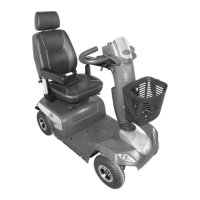
ARM PAD DEPTH ADJUSTMENT/
REPLACEMENT (FIGURE 5)
Adjustment
1. Remove the phillips screw from the rear of the arm-
rest pad and self-taping screw if FULL LENGTH ARM
PADS.
2. Depending on the desired arm pad depth, reposi-
tion the cantilever slide tube to one (1) of five (5)
positions for DESK LENGTH ARM PADS and into
the FIRST adjustment hole for the FULL LENGTH
ARM PADS.
3. Reattach the arm pad/cantilever slide tube to the
arm tube with existing hardware.
4. Repeat for the opposite side, if necessary.
Replacement
1. Remove the phillips screws from the armrest pad.
2. Replace with NEW armrest pad.
3. Secure with existing hardware.
NOTE: This Phillips Screw only needs to be
removed when Armrest Pad is replaced.
Cantilever Arm
Self-Tapping Screw
Full Length
Arm Pads
Phillips Screw
(Rear of Armrest
Pad)
Cantilever Slide Tube
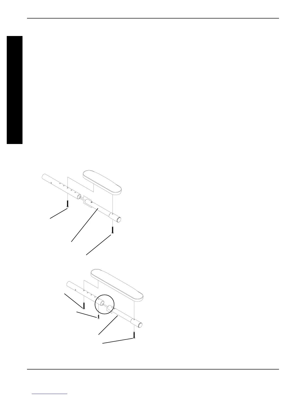
NOTE: This Phillips Screw only needs to be
removed when Armrest Pad is replaced.
Desk Length
Arm Pads
Phillips Screw
(Rear of Armrest
Pad)
Cantilever Slide Tube
FIGURE 5 - ARM PAD DEPTH ADJUSTMENT
NOTE: Only these Adjust-
ment Holes can be used.