22
This procedure includes the following:
Using/Installing/Height Adjustment/
Corresponding Arm Adjustment to Back Angle
Replacing/Repositioning the Locking
Mechanism in the Cantilever Arm
Arm Pad Depth Adjustment/Replacement
"T" Arm Installation
"T" Arm Height Adjustment
"T" Arm Width Adjustment
"T" Arm Pad Depth Adjustment
WARNING
NEVER try to lift or tip the wheelchair by the
cantilever arms or "T" arms, serious injury can
occur.
After adjustments and before use, make sure
all attaching hardware is securely tightened.
ARMSPROCEDURE 2
A
R
M
S
1. Slide the partially assembled cantilever arm
assembly w/mounting hardware through the back
cane. Make sure the adjustment plate is towards
the inside of the wheelchair.
NOTE:This includes top hex screw, coved wash-
ers and spacer (between adjustment plate and
cantilever arm).
2. Slide the bottom hex screw (w/coved washer)
through the adjustment plate and back cane.
3. Securely tighten the cantilever arm to the
wheelchair with two (2) locknuts and washers.
4. Adjust the angle of the cantilever arm, if neces-
sary. Refer to CORRESPONDING ARM ADJUST-
MENT TO BACK ANGLE in this section of the
manual.
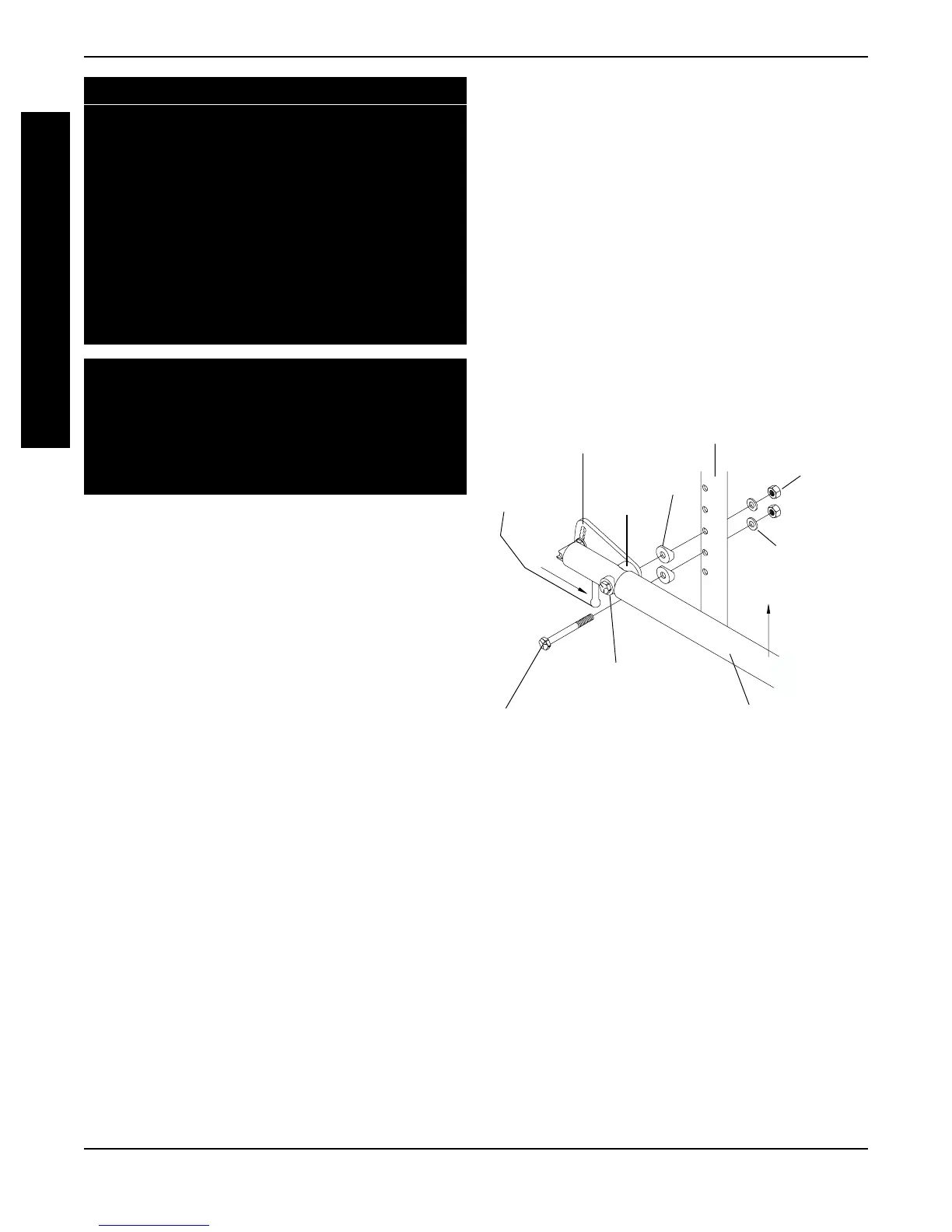
Installing/Height Adjustment (FIGURE 1)
NOTE: When removing the locknuts and washers
from the cantilever arm assembly, leave the top hex
screw, coved washers and spacer (between adjust-
ment plate and cantilever arm) in place.
USING/INSTALLING/HEIGHT
ADJUSTMENT/CORRESPONDING ARM
ADJUSTMENT TO BACK ANGLE
NOTE: The cantilever arms are designed for use
with the fixed height back canes only.
Using (FIGURE 1)
1. Pull the actuator of the locking mechanism
towards the front of the wheelchair.
2. While holding the actuator of the locking
mechanism, pull up on the cantilever arm.
NOTE: If necessary, the locking mechanism in
the cantilever arm can be repositioned so the
cantilever arm will open down instead of up.
Refer to REPLACING/REPOSITIONING THE
LOCKING MECHANISM IN THE CANTILEVER
ARM in this in this section of the manual.
3. To lock the cantilever arm, push down until there
is an audible click.
4. Pull up on the cantilever arm to make sure it is
locked in place.
Corresponding Arm Adjustment to Back Angle
(FIGURES 2 and 3)
NOTE: This adjustment is recommended if the
back angle has been changed.
1. Flip the cantilever arm up and out of the way.
2. Remove the locknut that secures the locking pin to
the arm adjustment plate (FIGURE 2).
3. Refer to FIGURE 3 to determine the mounting hole
in the arm adjustment plate that will be used to cor-
respond to the back angle.
4. Securely tighten the locking pin and washer to
the adjustment plate with a locknut.
5. Repeat STEPS 1-4 for the opposite side, if nec-
essary.
Washers
Locknuts
Back Cane
Actuator
Adjustment Plate
Cantilever Arm
Bottom Hex Screw
Top Hex Screw
and Coved Washer
Coved
Washers
Spacer
FIGURE 1- USING/INSTALLING/HEIGHT
ADJUSTMENT