40
CHANGING THE BACK ANGLE (FIGURE 16)
WARNING
The following procedure must be performed by
an authorized Invacare dealer or qualified tech-
nician.
The seat depth and back angle of the wheel-
chair, as well as the large wheel position directly
relate to the stability of the wheelchair. Any
change to one (1) or any combination of the
three (3) may cause the wheelchair to decrease
in stability. Use EXTREME caution when using
a new seating position for the first time.
94
o
is the maximum back angle that can be used
with the mini tilt option.
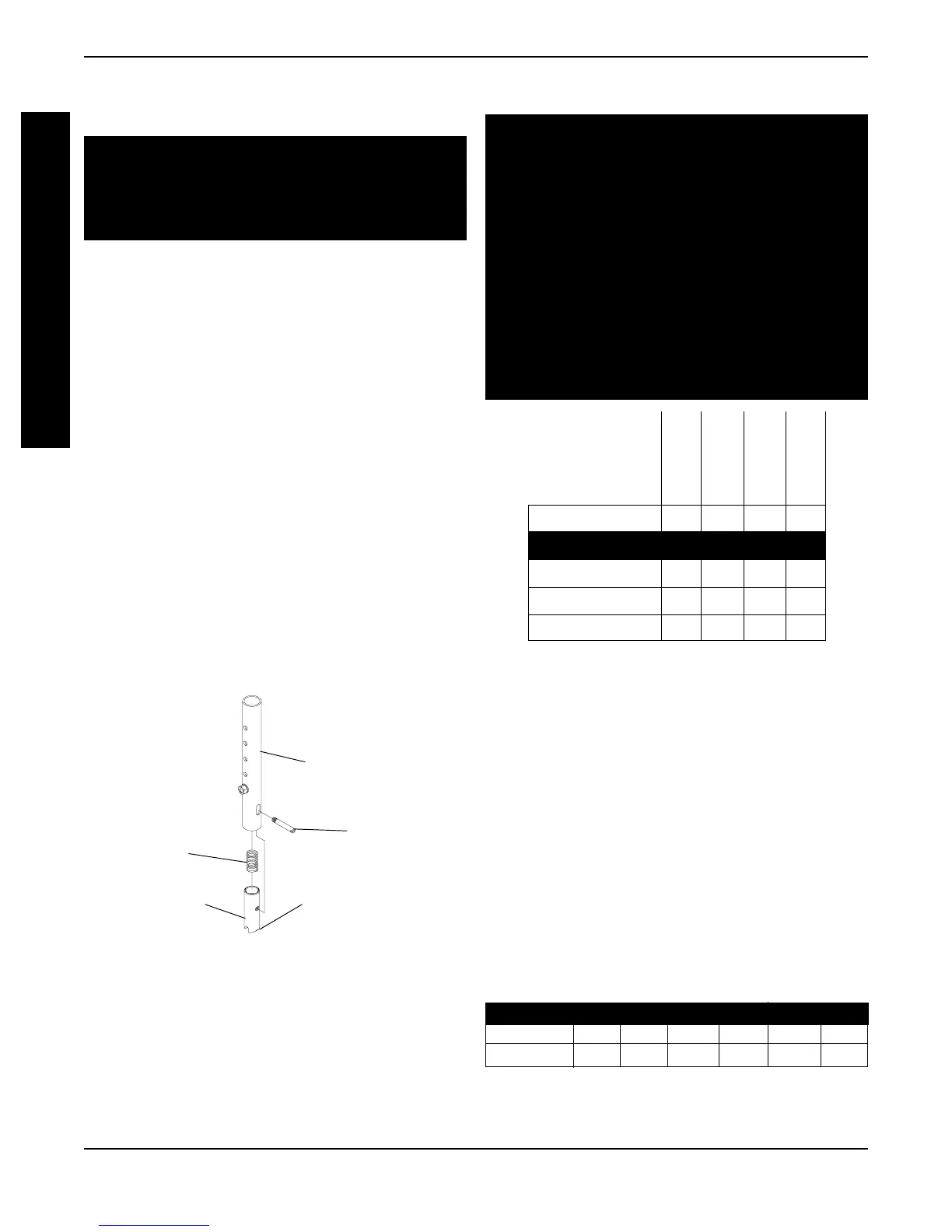
REPLACING THE LOCKING MECHANISM IN
THE BACK CANE (FIGURE 15)
CAUTION
The locking mechanism is spring loaded. Place
your free hand over the locking mechanism to
prevent the parts from springing out of the arm-
rest.
1. Move the back cane down and out of the way.
2. Remove the actuator from the locking mechanism.
3. Slowly let the locking mechanism and spring
slide out of the back cane.
NOTE: Inspect the spring and replace if neces-
sary.
4. Slide the new locking mechanism and spring
into the back cane.
5. Make sure the angled end of the locking mecha-
nism is pointing up towards the locking pin on
the adjustment plate.
6. Use Loctite 242 and securely tighten the actua-
tor into the locking mechanism.
7. To lock the back canes, pull up until there is an
audible click.
8. Push up on the back canes to make sure they
are locked in place.
Back Cane
Actuator
Spring
Locking
Mechanism
Angled Portion of
Locking Mechanism
FIGURE 15 - REPLACING THE LOCKING
MECHANISM IN THE BACK CANE
PROCEDURE 4 BACK
Back Angle
Rear Wheels
Seat Depth
Wheel Locks
PROCEDURE: 4537
Back Angle ● ✓✓✓
Rear Wheels ✓ ● ✓✓
Seat Depth ✓✓● ✓
Wheel Locks ✓✓✓●
NOTE: When adjusting the shaded area in the
left hand column, refer to the
✓✓
✓✓
✓ procedure to
ensure the proper stability, safety and handling
of the wheelchair.
1. Remove Seat Pan. Refer to REPLACING THE
SEAT PAN in PROCEDURE 2 of this manual.
2. Loosen, but do not remove the rear hex screw
that secures the back angle plate to the wheel-
chair frame.
3. Remove the front hex screw, washers, coved
washer and locknut that secure the back angle
plate to the wheelchair frame.
4. Position the back angle plate to one (1) of six
(6) back angles:
✪HOLE # 1 2 3 4 5 6
Non-Mini 86
o
90
o
94
o
98
o
102
o
106
o
Mini-Tilt 86
o
90
o
94
o
N/A N/A N/A
Allowable Back Angles
✪ ✪
✪ ✪
✪ Holes are numbered from the bottom to the top
for reference only. (There are no numbers on the
back angle plate).
B
A
C
K