21
FRONT RIGGINGS PROCEDURE 1
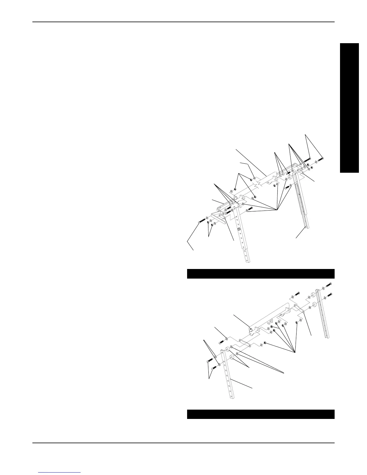
FIGURE 4 - TRANSFERRING SWING UNDER/
NON-SWING UNDER FOOTBOARDS
NON-SWING UNDER FOOTBOARD
Installing
1. Remove the two (2) hex screws and coved washers
that secure the existing front crossmember (in the
standard or reverse position) to the wheelchair frame.
2. Position the swing under/non-swing under footboard
to one (1) of the following positions on the wheel-
chair frame:
Standard Position - Three (3) mounting holes
from the front.
Reversed Position - Three (3) mounting holes
from the front.
3. Securely tighten to the wheelchair frame with the
existing two (2) hex screws and coved washers.
4. Adjust the swing under/non-swing udner footboard.
Refer to ADJUSTING THE SWING UNDER/NON-
SWING UNDER FOOTBOARD in this section of the
manual.
FOOTBOARD HEIGHT.
1. Remove the two (2) hex screws that secure the swing
under/non-swing under footboard to the support as-
semblies.
NOTE: Observe the angle of the swing under/non-
swing under footboard for reinstallation.
2. Position the swing under/non-swing under footboard
to the desired height to accommodate the user.
3. Reinstall the two (2) hex screws that secure the swing
under/non-swing under footboard to the support as-
semblies and securely tighten.
4. (Long Frame Only) - Height adjustment can
also be obtained by removing the two (2) hex
screws, washers, and locknuts and sliding the
inside channels up or down. Resecure the chan-
nels with the two (2) socket screws, washers,
and locknuts.
Support
Assemblies
Washers
Spacers
Locknuts
Link
Spacers
Washer
Footrest
Crossmember
SWING UNDER FOOTBOARD
2. Remove mounting screws, spacers, washers,
and locknuts that secure the support assem-
blies to the existing footrest crossmember.
3. (Swing Under Only) Secure the support assem-
blies and new release lever to the new longer
footrest crossmember with the existing hard-
ware.
4. Reinstall the new footboard. Refer to ADJUST-
ING/INSTALLING THE SWING UNDER/NON-
SWING UNDER FOOTBOARDS in this PRO-
CEDURE of this manual.
TRANSFERRING SWING UNDER /NON-
SWING UNDER FOOTBOARDS (FIGURE 4)
NOTE: This is necessary when adjusting the
width of the COMET.
1. Remove footboard. Refer to ADJUSTING/IN-
STALLING THE SWING UNDER/NON-SWING
UNDER FOOTBOARD in this PROCEDURE of
this manual.
Mounting
Screws
F
R
O
N
T
R
I
G
G
I
N
G
S
Washers
Spacers
Washers
Locknuts
Washers
Spacers
Link
Link
Support
Assemblies
Locknuts
Release
Lever
Footrest
Crossmember
Mounting Screws
Mounting
Screws




 To Next Page