53
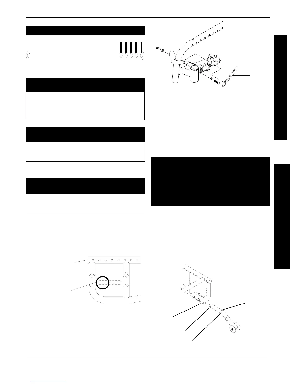
FIGURE 5 - INSTALLING THE ANTI-TIPPERS
Anti-tipper
Mount
2. Adjust the anti-tippers. Refer to ADJUSTING THE
ANTI-TIPPERS in this section of the manual.
Anti-tipper
Release Buttons
Locking Pins
Installing the Anti-Tippers
1. Press the release buttons IN and insert the anti-
tippers with the anti-tipper wheels pointing toward
the ground/floor into the anti-tipper mount until
the two (2) locking pins are secured in place
(FIGURE 5).
WARNING
Anti-tippers MUST be fully engaged and spring
buttons fully protruding out of adjustment holes
BEFORE using the wheelchair.
Make sure the anti-tipper wheels are pointing
towards the ground/floor BEFORE using the
wheelchair.
1 2 3 4 5
WHEEL LOCK LINK
For 16-inch Wheels:
5th Frame Mounting Hole From Front of Wheelchair
Axle Mounting Hole Link No.
11
22
33
For 20-inch Wheels:
5th Frame Mounting Hole From Front of Wheelchair
Axle Mounting Hole Link No.
1,2,3 5
For 20, 22, 24-inch Wheels:
6th Frame Mounting Hole From Front of Wheelchair
Axle Mounting Hole Link No.
1,2,3 5
6. Secure link to existing wheel lock in the position
determined in STEP 3 with button screw,
washers and locknut provided (FIGURE 4).
FIGURE 3 - WHEEL LOCK LINK MOUNTING
POSITIONS
Link Mounting
Positions Step 8
FIGURE 4 - WHEEL LOCK LINK MOUNTING
7. Adjust wheel locks if necessary. Refer to WHEEL
LOCK ADJUSTMENT in this PROCEDURE of the
manual.
8. Repeat procedure for opposite side.
INSTALLING/ADJUSTING THE ANTI-TIPPERS
(FIGURES 5 AND 6)
Axle Mounting Hole
1st, 2nd or 3rd Hole
from FRONT of
Wheelchair
Front of Wheelchair
in Reverse Position
SHORT FRAME
LONG FRAME
NOTE: Installation of the wheel locks requires
some adjustment. Refer to ADJUSTING THE
WHEEL LOCKS in this procedure.
PROCEDURE 7WHEEL LOCKS/ANTI-TIPPERS
A
N
T
I
T
I
P
P
E
R
S
W
H
E
E
L
L
O
C
K
S