Optidrive Eco User Guide Revision 2.01
3.4. Guidelines for Enclosure mounting (IP20 Units)
IP20 drives are suitable for use in pollution degree 1 environments, according to IEC-664-1. For pollution degree 2 or higher
environments, drives should be mounted in a suitable control cabinet with sufficient ingress protection to maintain a pollution
degree 1 environment around the drive.
Enclosures should be made from a thermally conductive material.
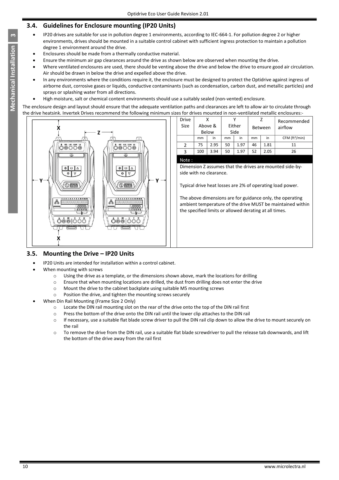
Ensure the minimum air gap clearances around the drive as shown below are observed when mounting the drive.
Where ventilated enclosures are used, there should be venting above the drive and below the drive to ensure good air circulation.
Air should be drawn in below the drive and expelled above the drive.
In any environments where the conditions require it, the enclosure must be designed to protect the Optidrive against ingress of
airborne dust, corrosive gases or liquids, conductive contaminants (such as condensation, carbon dust, and metallic particles) and
sprays or splashing water from all directions.
High moisture, salt or chemical content environments should use a suitably sealed (non-vented) enclosure.
The enclosure design and layout should ensure that the adequate ventilation paths and clearances are left to allow air to circulate through
the drive heatsink. Invertek Drives recommend the following minimum sizes for drives mounted in non-ventilated metallic enclosures:-
Dimension Z assumes that the drives are mounted side-by-
side with no clearance.
Typical drive heat losses are 2% of operating load power.
The above dimensions are for guidance only, the operating
ambient temperature of the drive MUST be maintained within
the specified limits or allowed derating at all times.
3.5. Mounting the Drive – IP20 Units
IP20 Units are intended for installation within a control cabinet.
When mounting with screws
o Using the drive as a template, or the dimensions shown above, mark the locations for drilling
o Ensure that when mounting locations are drilled, the dust from drilling does not enter the drive
o Mount the drive to the cabinet backplate using suitable M5 mounting screws
o Position the drive, and tighten the mounting screws securely
When Din Rail Mounting (Frame Size 2 Only)
o Locate the DIN rail mounting slot on the rear of the drive onto the top of the DIN rail first
o Press the bottom of the drive onto the DIN rail until the lower clip attaches to the DIN rail
o If necessary, use a suitable flat blade screw driver to pull the DIN rail clip down to allow the drive to mount securely on
the rail
o To remove the drive from the DIN rail, use a suitable flat blade screwdriver to pull the release tab downwards, and lift
the bottom of the drive away from the rail first

 Loading...

