Optidrive Eco User Guide Revision 2.01
8. Parameters
8.1. Parameter Set Overview
The Optidrive Eco Extended Parameter set consists of 7 groups as follows:
Group 1 – Basic Parameter Set
Group 2 – Extended Parameter Set
Group 3 – User PID Control Parameter Set
Group 4 – Motor Control Parameters
Group 5 – Field Bus Communications Parameter Set
Group 8 – Application Specific Functions Parameter Set
Group 0 –Monitoring and Diagnostic Parameters (Read Only)
When the Optidrive is reset to factory defaults, or is in its factory supplied state, only Group 1 Parameters can be accessed. In order to allow
access to parameters from the higher level groups, P1-14 must be set to the same value as P2-40 (Default setting = 101). With this setting,
parameter groups 1 – 5 and group 8 can be accessed, along with the first 39 parameters in Group 0. These parameters are listed in the tables
below.
For advanced parameter access, P1-14 can be set to the same value as P6-30 (Default setting = 201), which allows access to all parameter
groups and ranges. Advanced parameter descriptions are listed in the advanced user guide.
Values given in brackets () are default settings for horsepower rated drive models.
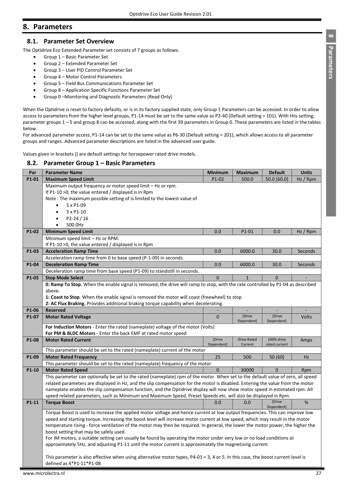
8.2. Parameter Group 1 – Basic Parameters
Maximum output frequency or motor speed limit – Hz or rpm.
If P1-10 >0, the value entered / displayed is in Rpm
Note : The maximum possible setting of is limited to the lowest value of
5 x P1-09
5 x P1-10
P2-24 / 16
500.0Hz
Minimum speed limit – Hz or RPM.
If P1-10 >0, the value entered / displayed is in Rpm
Acceleration ramp time from 0 to base speed (P-1-09) in seconds.
Deceleration ramp time from base speed (P1-09) to standstill in seconds.
0: Ramp To Stop. When the enable signal is removed, the drive will ramp to stop, with the rate controlled by P1-04 as described
above.
1: Coast to Stop. When the enable signal is removed the motor will coast (freewheel) to stop
2: AC Flux Braking. Provides additional braking torque capability when decelerating.
For Induction Motors - Enter the rated (nameplate) voltage of the motor (Volts)
For PM & BLDC Motors - Enter the back EMF at rated motor speed
This parameter should be set to the rated (nameplate) current of the motor
This parameter should be set to the rated (nameplate) frequency of the motor
This parameter can optionally be set to the rated (nameplate) rpm of the motor. When set to the default value of zero, all speed
related parameters are displayed in Hz, and the slip compensation for the motor is disabled. Entering the value from the motor
nameplate enables the slip compensation function, and the Optidrive display will now show motor speed in estimated rpm. All
speed related parameters, such as Minimum and Maximum Speed, Preset Speeds etc. will also be displayed in Rpm.
Torque Boost is used to increase the applied motor voltage and hence current at low output frequencies. This can improve low
speed and starting torque. Increasing the boost level will increase motor current at low speed, which may result in the motor
temperature rising - force ventilation of the motor may then be required. In general, the lower the motor power, the higher the
boost setting that may be safely used.
For IM motors, a suitable setting can usually be found by operating the motor under very low or no load conditions at
approximately 5Hz, and adjusting P1-11 until the motor current is approximately the magnetising current
This parameter is also effective when using alternative motor types, P4-01 = 3, 4 or 5. In this case, the boost current level is
defined as 4*P1-11*P1-08

 Loading...


