Optidrive Eco User Guide Revision 2.01
4.5.2. Motor Thermistor Connection
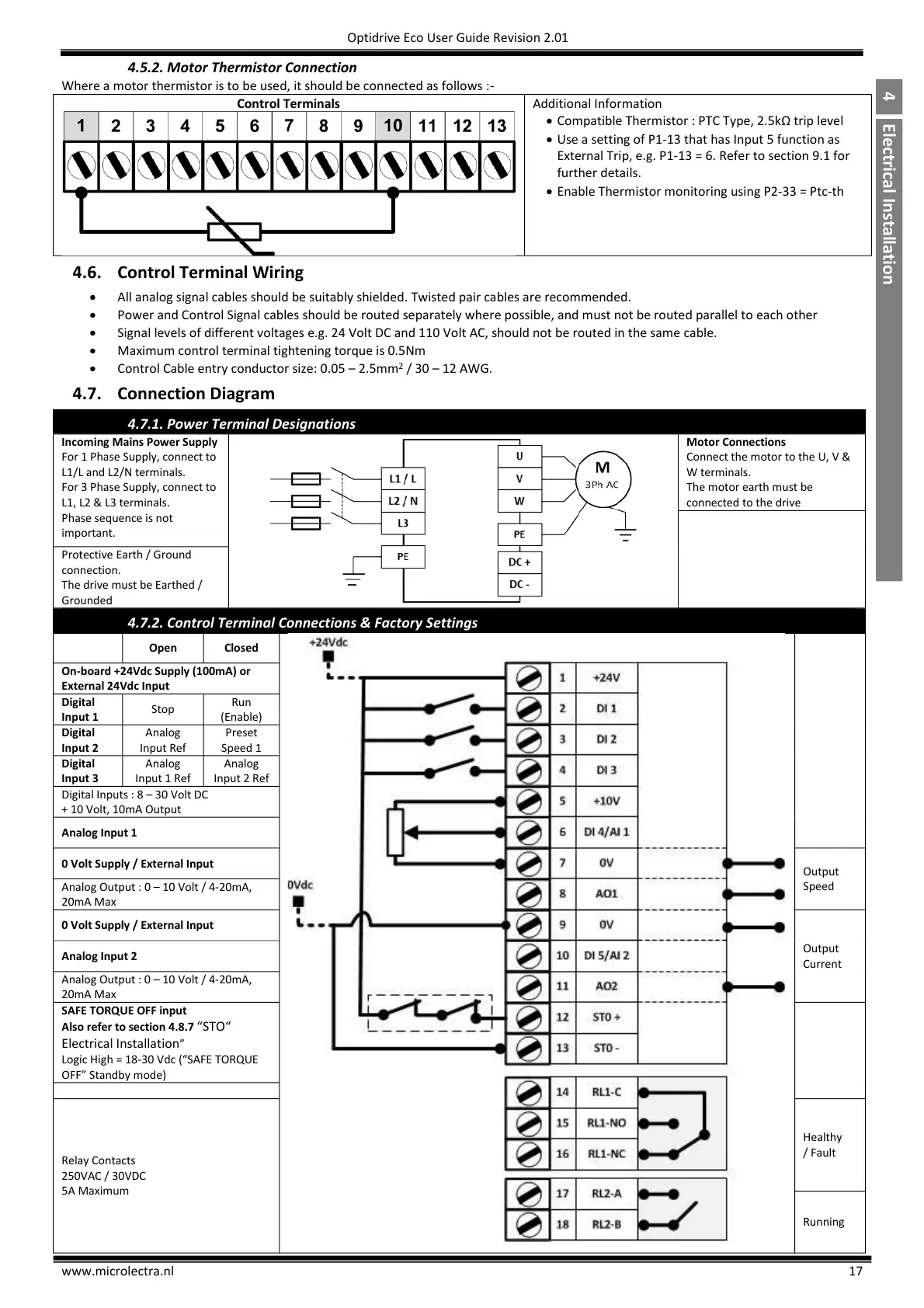
Where a motor thermistor is to be used, it should be connected as follows :-
Compatible Thermistor : PTC Type, 2.5kΩ trip level
Use a setting of P1-13 that has Input 5 function as
External Trip, e.g. P1-13 = 6. Refer to section 9.1 for
further details.
Enable Thermistor monitoring using P2-33 = Ptc-th
4.6. Control Terminal Wiring
All analog signal cables should be suitably shielded. Twisted pair cables are recommended.
Power and Control Signal cables should be routed separately where possible, and must not be routed parallel to each other
Signal levels of different voltages e.g. 24 Volt DC and 110 Volt AC, should not be routed in the same cable.
Maximum control terminal tightening torque is 0.5Nm
Control Cable entry conductor size: 0.05 – 2.5mm
2
/ 30 – 12 AWG.
4.7. Connection Diagram
4.7.1. Power Terminal Designations
Incoming Mains Power Supply
For 1 Phase Supply, connect to
L1/L and L2/N terminals.
For 3 Phase Supply, connect to
L1, L2 & L3 terminals.
Phase sequence is not
important.
Connect the motor to the U, V &
W terminals.
The motor earth must be
connected to the drive
Protective Earth / Ground
connection.
The drive must be Earthed /
Grounded
4.7.2. Control Terminal Connections & Factory Settings
On-board +24Vdc Supply (100mA) or
External 24Vdc Input
Digital Inputs : 8 – 30 Volt DC
+ 10 Volt, 10mA Output
0 Volt Supply / External Input
Analog Output : 0 – 10 Volt / 4-20mA,
20mA Max
0 Volt Supply / External Input
Analog Output : 0 – 10 Volt / 4-20mA,
20mA Max
Also refer to section 4.8.7 “STO“
Electrical Installation”,
Logic High = 18-30,Vdc,(“S;FE,TORQUE,
OFF”,Standby,mode)

 Loading...

