Optidrive Eco User Guide Revision 2.01
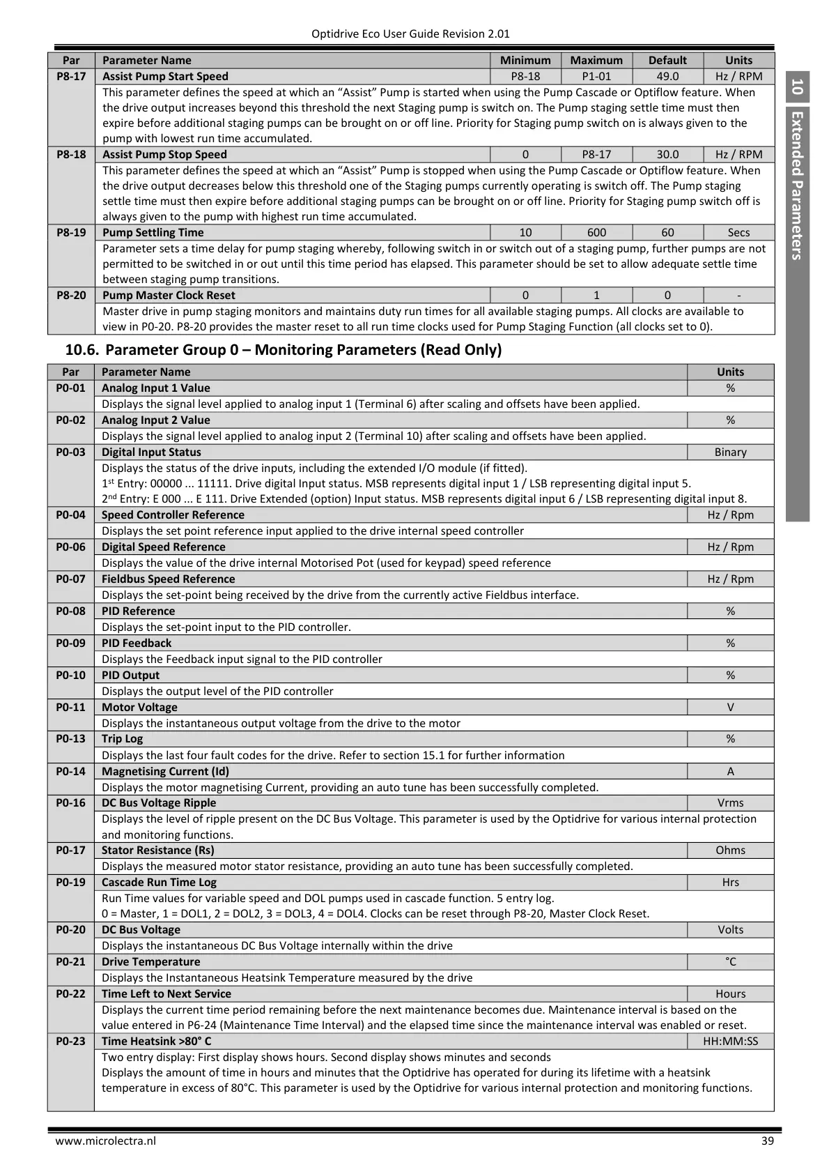
This,parameter,defines,the,speed,at,which,an,“;ssist”,Pump,is,started,when,using,the,Pump,Cascade,or,Optiflow,feature. When
the drive output increases beyond this threshold the next Staging pump is switch on. The Pump staging settle time must then
expire before additional staging pumps can be brought on or off line. Priority for Staging pump switch on is always given to the
pump with lowest run time accumulated.
This,parameter,defines,the,speed,at,which,an,“;ssist”,Pump,is,stopped,when,using,the,Pump,Cascade,or,Optiflow,feature. When
the drive output decreases below this threshold one of the Staging pumps currently operating is switch off. The Pump staging
settle time must then expire before additional staging pumps can be brought on or off line. Priority for Staging pump switch off is
always given to the pump with highest run time accumulated.
Parameter sets a time delay for pump staging whereby, following switch in or switch out of a staging pump, further pumps are not
permitted to be switched in or out until this time period has elapsed. This parameter should be set to allow adequate settle time
between staging pump transitions.
Master drive in pump staging monitors and maintains duty run times for all available staging pumps. All clocks are available to
view in P0-20. P8-20 provides the master reset to all run time clocks used for Pump Staging Function (all clocks set to 0).
10.6. Parameter Group 0 – Monitoring Parameters (Read Only)
Displays the signal level applied to analog input 1 (Terminal 6) after scaling and offsets have been applied.
Displays the signal level applied to analog input 2 (Terminal 10) after scaling and offsets have been applied.
Displays the status of the drive inputs, including the extended I/O module (if fitted).
Entry: 00000 ... 11111. Drive digital Input status. MSB represents digital input 1 / LSB representing digital input 5.
2
Entry: E 000 ... E 111. Drive Extended (option) Input status. MSB represents digital input 6 / LSB representing digital input 8.
Speed Controller Reference
Displays the set point reference input applied to the drive internal speed controller
Displays the value of the drive internal Motorised Pot (used for keypad) speed reference
Displays the set-point being received by the drive from the currently active Fieldbus interface.
Displays the set-point input to the PID controller.
Displays the Feedback input signal to the PID controller
Displays the output level of the PID controller
Displays the instantaneous output voltage from the drive to the motor
Displays the last four fault codes for the drive. Refer to section 15.1 for further information
Displays the motor magnetising Current, providing an auto tune has been successfully completed.
Displays the level of ripple present on the DC Bus Voltage. This parameter is used by the Optidrive for various internal protection
and monitoring functions.
Displays the measured motor stator resistance, providing an auto tune has been successfully completed.
Run Time values for variable speed and DOL pumps used in cascade function. 5 entry log.
0 = Master, 1 = DOL1, 2 = DOL2, 3 = DOL3, 4 = DOL4. Clocks can be reset through P8-20, Master Clock Reset.
Displays the instantaneous DC Bus Voltage internally within the drive
Displays the Instantaneous Heatsink Temperature measured by the drive
Time Left to Next Service
Displays the current time period remaining before the next maintenance becomes due. Maintenance interval is based on the
value entered in P6-24 (Maintenance Time Interval) and the elapsed time since the maintenance interval was enabled or reset.
Two entry display: First display shows hours. Second display shows minutes and seconds
Displays the amount of time in hours and minutes that the Optidrive has operated for during its lifetime with a heatsink
temperature in excess of 80°C. This parameter is used by the Optidrive for various internal protection and monitoring functions.

 Loading...

