Optidrive Eco User Guide Revision 2.01
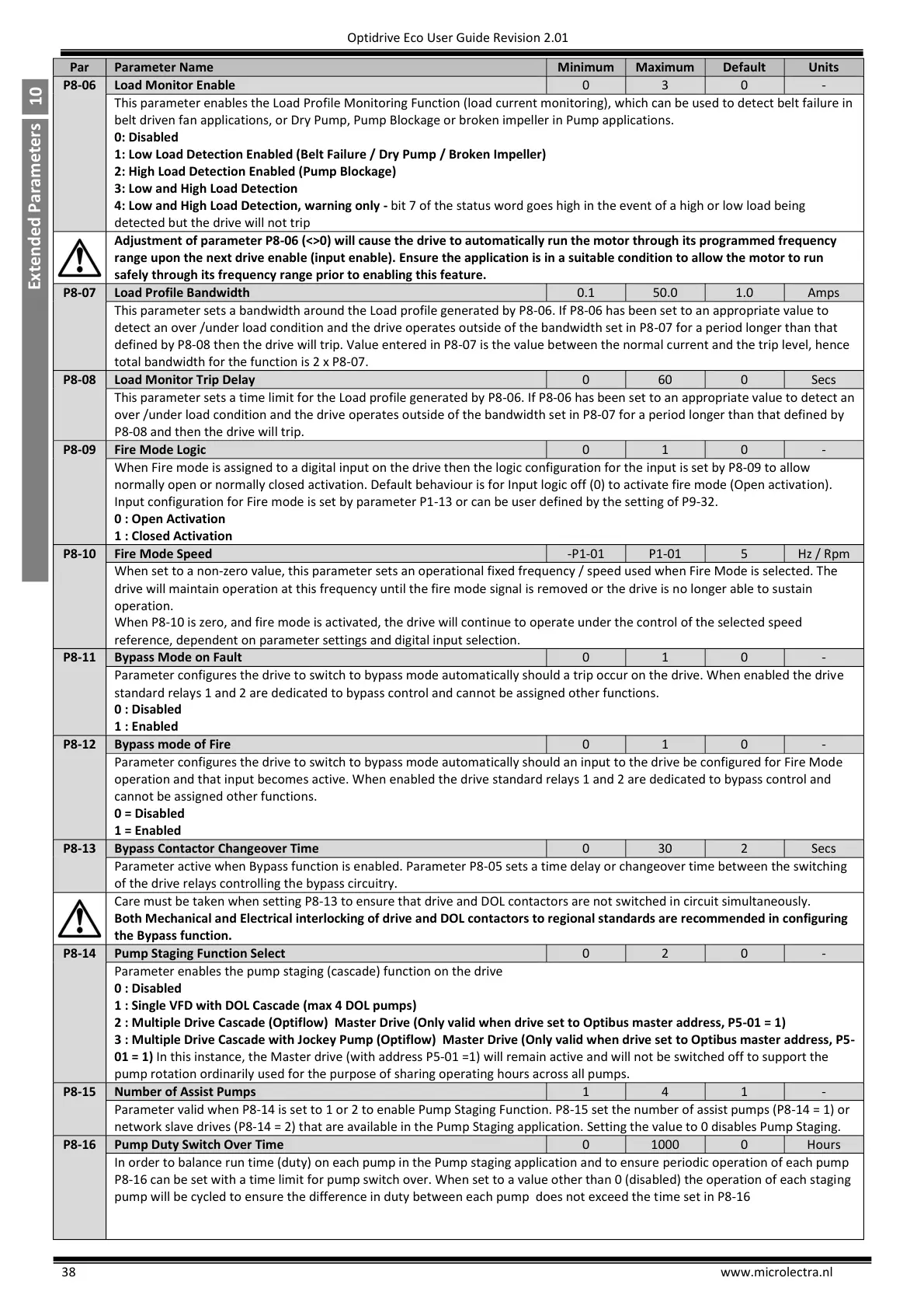
This parameter enables the Load Profile Monitoring Function (load current monitoring), which can be used to detect belt failure in
belt driven fan applications, or Dry Pump, Pump Blockage or broken impeller in Pump applications.
0: Disabled
1: Low Load Detection Enabled (Belt Failure / Dry Pump / Broken Impeller)
2: High Load Detection Enabled (Pump Blockage)
3: Low and High Load Detection
4: Low and High Load Detection, warning only - bit 7 of the status word goes high in the event of a high or low load being
detected but the drive will not trip
Adjustment of parameter P8-06 (<>0) will cause the drive to automatically run the motor through its programmed frequency
range upon the next drive enable (input enable). Ensure the application is in a suitable condition to allow the motor to run
safely through its frequency range prior to enabling this feature.
This parameter sets a bandwidth around the Load profile generated by P8-06. If P8-06 has been set to an appropriate value to
detect an over /under load condition and the drive operates outside of the bandwidth set in P8-07 for a period longer than that
defined by P8-08 then the drive will trip. Value entered in P8-07 is the value between the normal current and the trip level, hence
total bandwidth for the function is 2 x P8-07.
This parameter sets a time limit for the Load profile generated by P8-06. If P8-06 has been set to an appropriate value to detect an
over /under load condition and the drive operates outside of the bandwidth set in P8-07 for a period longer than that defined by
P8-08 and then the drive will trip.
When Fire mode is assigned to a digital input on the drive then the logic configuration for the input is set by P8-09 to allow
normally open or normally closed activation. Default behaviour is for Input logic off (0) to activate fire mode (Open activation).
Input configuration for Fire mode is set by parameter P1-13 or can be user defined by the setting of P9-32.
0 : Open Activation
1 : Closed Activation
When set to a non-zero value, this parameter sets an operational fixed frequency / speed used when Fire Mode is selected. The
drive will maintain operation at this frequency until the fire mode signal is removed or the drive is no longer able to sustain
operation.
When P8-10 is zero, and fire mode is activated, the drive will continue to operate under the control of the selected speed
reference, dependent on parameter settings and digital input selection.
Parameter configures the drive to switch to bypass mode automatically should a trip occur on the drive. When enabled the drive
standard relays 1 and 2 are dedicated to bypass control and cannot be assigned other functions.
Parameter configures the drive to switch to bypass mode automatically should an input to the drive be configured for Fire Mode
operation and that input becomes active. When enabled the drive standard relays 1 and 2 are dedicated to bypass control and
cannot be assigned other functions.
Bypass Contactor Changeover Time
Parameter active when Bypass function is enabled. Parameter P8-05 sets a time delay or changeover time between the switching
of the drive relays controlling the bypass circuitry.
Care must be taken when setting P8-13 to ensure that drive and DOL contactors are not switched in circuit simultaneously.
Both Mechanical and Electrical interlocking of drive and DOL contactors to regional standards are recommended in configuring
the Bypass function.
Pump Staging Function Select
Parameter enables the pump staging (cascade) function on the drive
0 : Disabled
1 : Single VFD with DOL Cascade (max 4 DOL pumps)
2 : Multiple Drive Cascade (Optiflow) Master Drive (Only valid when drive set to Optibus master address, P5-01 = 1)
3 : Multiple Drive Cascade with Jockey Pump (Optiflow) Master Drive (Only valid when drive set to Optibus master address, P5-
01 = 1) In this instance, the Master drive (with address P5-01 =1) will remain active and will not be switched off to support the
pump rotation ordinarily used for the purpose of sharing operating hours across all pumps.
Parameter valid when P8-14 is set to 1 or 2 to enable Pump Staging Function. P8-15 set the number of assist pumps (P8-14 = 1) or
network slave drives (P8-14 = 2) that are available in the Pump Staging application. Setting the value to 0 disables Pump Staging.
Pump Duty Switch Over Time
In order to balance run time (duty) on each pump in the Pump staging application and to ensure periodic operation of each pump
P8-16 can be set with a time limit for pump switch over. When set to a value other than 0 (disabled) the operation of each staging
pump will be cycled to ensure the difference in duty between each pump does not exceed the time set in P8-16

 Loading...


