Optidrive Eco User Guide Revision 2.01
11.2. Modbus RTU Communications
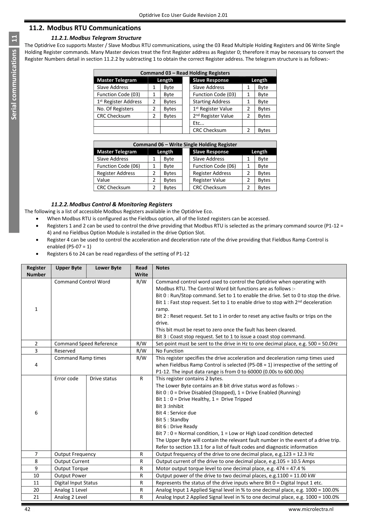
11.2.1. Modbus Telegram Structure
The Optidrive Eco supports Master / Slave Modbus RTU communications, using the 03 Read Multiple Holding Registers and 06 Write Single
Holding Register commands. Many Master devices treat the first Register address as Register 0; therefore it may be necessary to convert the
Register Numbers detail in section 11.2.2 by subtracting 1 to obtain the correct Register address. The telegram structure is as follows:-
Command 03 – Read Holding Registers
Command 06 – Write Single Holding Register
11.2.2. Modbus Control & Monitoring Registers
The following is a list of accessible Modbus Registers available in the Optidrive Eco.
When Modbus RTU is configured as the Fieldbus option, all of the listed registers can be accessed.
Registers 1 and 2 can be used to control the drive providing that Modbus RTU is selected as the primary command source (P1-12 =
4) and no Fieldbus Option Module is installed in the drive Option Slot.
Register 4 can be used to control the acceleration and deceleration rate of the drive providing that Fieldbus Ramp Control is
enabled (P5-07 = 1)
Registers 6 to 24 can be read regardless of the setting of P1-12
Command control word used to control the Optidrive when operating with
Modbus RTU. The Control Word bit functions are as follows :-
Bit 0 : Run/Stop command. Set to 1 to enable the drive. Set to 0 to stop the drive.
Bit 1 : Fast stop request. Set to 1 to enable drive to stop with 2
nd
deceleration
ramp.
Bit 2 : Reset request. Set to 1 in order to reset any active faults or trips on the
drive.
This bit must be reset to zero once the fault has been cleared.
Bit 3 : Coast stop request. Set to 1 to issue a coast stop command.
Set-point must be sent to the drive in Hz to one decimal place, e.g. 500 = 50.0Hz
This register specifies the drive acceleration and deceleration ramp times used
when Fieldbus Ramp Control is selected (P5-08 = 1) irrespective of the setting of
P1-12. The input data range is from 0 to 60000 (0.00s to 600.00s)
This register contains 2 bytes.
The Lower Byte contains an 8 bit drive status word as follows :-
Bit 0 : 0 = Drive Disabled (Stopped), 1 = Drive Enabled (Running)
Bit 1 : 0 = Drive Healthy, 1 = Drive Tripped
Bit 3 :Inhibit
Bit 4 : Service due
Bit 5 : Standby
Bit 6 : Drive Ready
Bit 7 : 0 = Normal condition, 1 = Low or High Load condition detected
The Upper Byte will contain the relevant fault number in the event of a drive trip.
Refer to section 13.1 for a list of fault codes and diagnostic information
Output frequency of the drive to one decimal place, e.g.123 = 12.3 Hz
Output current of the drive to one decimal place, e.g.105 = 10.5 Amps
Motor output torque level to one decimal place, e.g. 474 = 47.4 %
Output power of the drive to two decimal places, e.g.1100 = 11.00 kW
Represents the status of the drive inputs where Bit 0 = Digital Input 1 etc.
Analog Input 1 Applied Signal level in % to one decimal place, e.g. 1000 = 100.0%
Analog Input 2 Applied Signal level in % to one decimal place, e.g. 1000 = 100.0%

 Loading...


