Optidrive Eco User Guide Revision 2.01
10.Extended Parameters
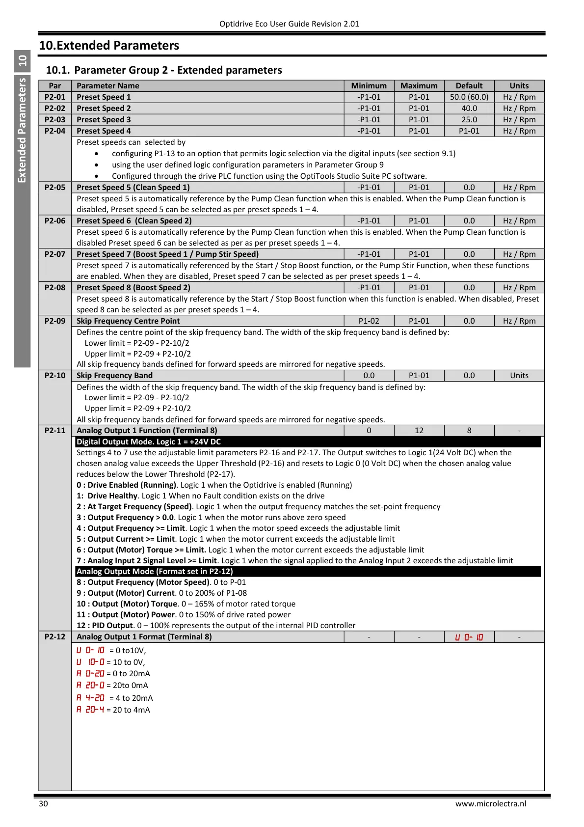
10.1. Parameter Group 2 - Extended parameters
Preset speeds can selected by
configuring P1-13 to an option that permits logic selection via the digital inputs (see section 9.1)
using the user defined logic configuration parameters in Parameter Group 9
Configured through the drive PLC function using the OptiTools Studio Suite PC software.
Preset Speed 5 (Clean Speed 1)
Preset speed 5 is automatically reference by the Pump Clean function when this is enabled. When the Pump Clean function is
disabled, Preset speed 5 can be selected as per preset speeds 1 – 4.
Preset Speed 6 (Clean Speed 2)
Preset speed 6 is automatically reference by the Pump Clean function when this is enabled. When the Pump Clean function is
disabled Preset speed 6 can be selected as per as per preset speeds 1 – 4.
Preset Speed 7 (Boost Speed 1 / Pump Stir Speed)
Preset speed 7 is automatically referenced by the Start / Stop Boost function, or the Pump Stir Function, when these functions
are enabled. When they are disabled, Preset speed 7 can be selected as per preset speeds 1 – 4.
Preset Speed 8 (Boost Speed 2)
Preset speed 8 is automatically reference by the Start / Stop Boost function when this function is enabled. When disabled, Preset
speed 8 can be selected as per preset speeds 1 – 4.
Skip Frequency Centre Point
Defines the centre point of the skip frequency band. The width of the skip frequency band is defined by:
Lower limit = P2-09 - P2-10/2
Upper limit = P2-09 + P2-10/2
All skip frequency bands defined for forward speeds are mirrored for negative speeds.
Defines the width of the skip frequency band. The width of the skip frequency band is defined by:
Lower limit = P2-09 - P2-10/2
Upper limit = P2-09 + P2-10/2
All skip frequency bands defined for forward speeds are mirrored for negative speeds.
Analog Output 1 Function (Terminal 8)
Digital Output Mode. Logic 1 = +24V DC
Settings 4 to 7 use the adjustable limit parameters P2-16 and P2-17. The Output switches to Logic 1(24 Volt DC) when the
chosen analog value exceeds the Upper Threshold (P2-16) and resets to Logic 0 (0 Volt DC) when the chosen analog value
reduces below the Lower Threshold (P2-17).
0 : Drive Enabled (Running). Logic 1 when the Optidrive is enabled (Running)
1: Drive Healthy. Logic 1 When no Fault condition exists on the drive
2 : At Target Frequency (Speed). Logic 1 when the output frequency matches the set-point frequency
3 : Output Frequency > 0.0. Logic 1 when the motor runs above zero speed
4 : Output Frequency >= Limit. Logic 1 when the motor speed exceeds the adjustable limit
5 : Output Current >= Limit. Logic 1 when the motor current exceeds the adjustable limit
6 : Output (Motor) Torque >= Limit. Logic 1 when the motor current exceeds the adjustable limit
7 : Analog Input 2 Signal Level >= Limit. Logic 1 when the signal applied to the Analog Input 2 exceeds the adjustable limit
Analog Output Mode (Format set in P2-12)
8 : Output Frequency (Motor Speed). 0 to P-01
9 : Output (Motor) Current. 0 to 200% of P1-08
10 : Output (Motor) Torque. 0 – 165% of motor rated torque
11 : Output (Motor) Power. 0 to 150% of drive rated power
12 : PID Output. 0 – 100% represents the output of the internal PID controller
Analog Output 1 Format (Terminal 8)
= 10 to 0V,
= 0 to 20mA
= 20to 0mA
= 4 to 20mA
= 20 to 4mA

 Loading...

