Optidrive Eco User Guide Revision 2.01
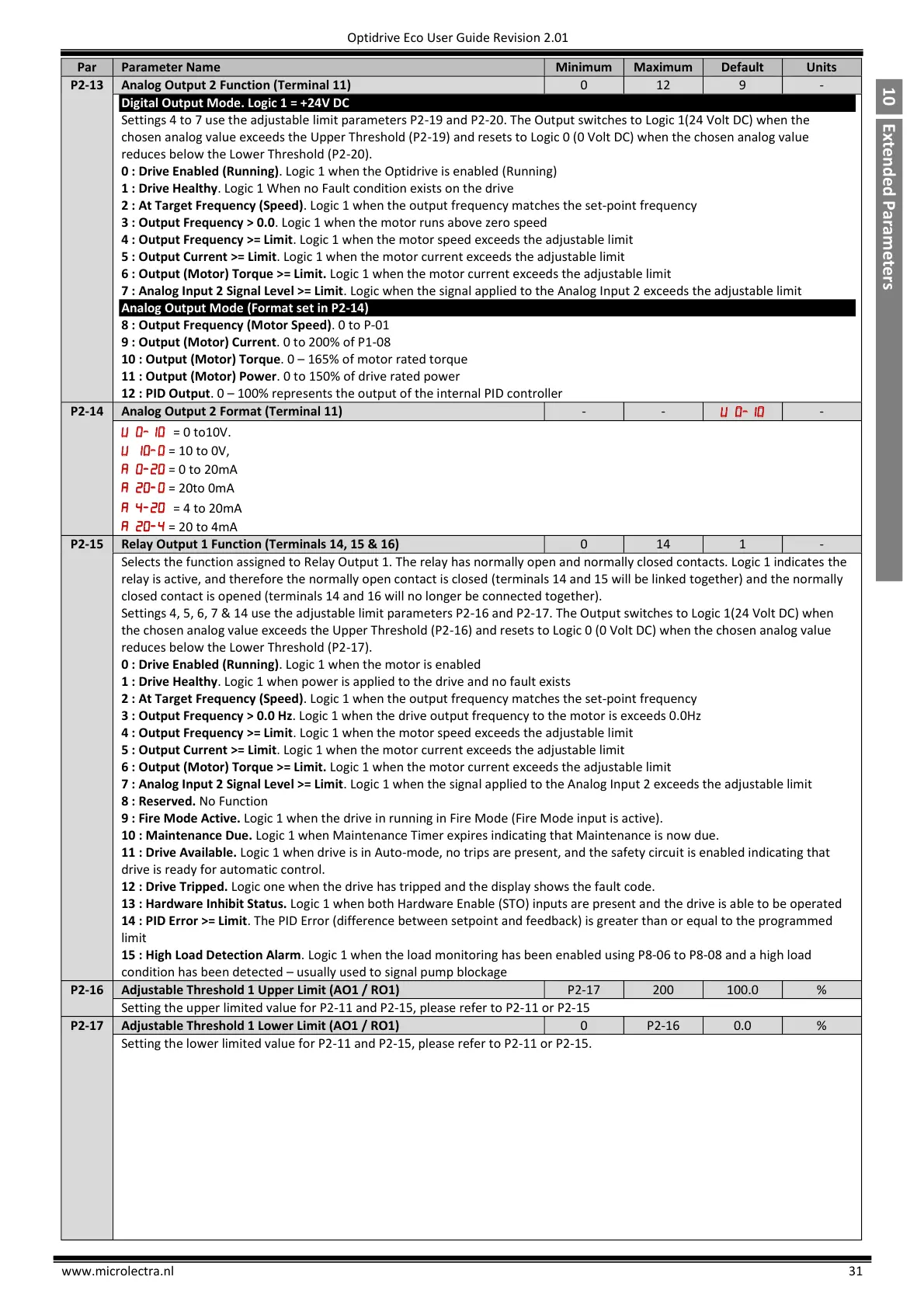
Analog Output 2 Function (Terminal 11)
Digital Output Mode. Logic 1 = +24V DC
Settings 4 to 7 use the adjustable limit parameters P2-19 and P2-20. The Output switches to Logic 1(24 Volt DC) when the
chosen analog value exceeds the Upper Threshold (P2-19) and resets to Logic 0 (0 Volt DC) when the chosen analog value
reduces below the Lower Threshold (P2-20).
0 : Drive Enabled (Running). Logic 1 when the Optidrive is enabled (Running)
1 : Drive Healthy. Logic 1 When no Fault condition exists on the drive
2 : At Target Frequency (Speed). Logic 1 when the output frequency matches the set-point frequency
3 : Output Frequency > 0.0. Logic 1 when the motor runs above zero speed
4 : Output Frequency >= Limit. Logic 1 when the motor speed exceeds the adjustable limit
5 : Output Current >= Limit. Logic 1 when the motor current exceeds the adjustable limit
6 : Output (Motor) Torque >= Limit. Logic 1 when the motor current exceeds the adjustable limit
7 : Analog Input 2 Signal Level >= Limit. Logic when the signal applied to the Analog Input 2 exceeds the adjustable limit
Analog Output Mode (Format set in P2-14)
8 : Output Frequency (Motor Speed). 0 to P-01
9 : Output (Motor) Current. 0 to 200% of P1-08
10 : Output (Motor) Torque. 0 – 165% of motor rated torque
11 : Output (Motor) Power. 0 to 150% of drive rated power
12 : PID Output. 0 – 100% represents the output of the internal PID controller
Analog Output 2 Format (Terminal 11)
= 10 to 0V,
= 0 to 20mA
= 20to 0mA
= 4 to 20mA
= 20 to 4mA
Relay Output 1 Function (Terminals 14, 15 & 16)
Selects the function assigned to Relay Output 1. The relay has normally open and normally closed contacts. Logic 1 indicates the
relay is active, and therefore the normally open contact is closed (terminals 14 and 15 will be linked together) and the normally
closed contact is opened (terminals 14 and 16 will no longer be connected together).
Settings 4, 5, 6, 7 & 14 use the adjustable limit parameters P2-16 and P2-17. The Output switches to Logic 1(24 Volt DC) when
the chosen analog value exceeds the Upper Threshold (P2-16) and resets to Logic 0 (0 Volt DC) when the chosen analog value
reduces below the Lower Threshold (P2-17).
0 : Drive Enabled (Running). Logic 1 when the motor is enabled
1 : Drive Healthy. Logic 1 when power is applied to the drive and no fault exists
2 : At Target Frequency (Speed). Logic 1 when the output frequency matches the set-point frequency
3 : Output Frequency > 0.0 Hz. Logic 1 when the drive output frequency to the motor is exceeds 0.0Hz
4 : Output Frequency >= Limit. Logic 1 when the motor speed exceeds the adjustable limit
5 : Output Current >= Limit. Logic 1 when the motor current exceeds the adjustable limit
6 : Output (Motor) Torque >= Limit. Logic 1 when the motor current exceeds the adjustable limit
7 : Analog Input 2 Signal Level >= Limit. Logic 1 when the signal applied to the Analog Input 2 exceeds the adjustable limit
8 : Reserved. No Function
9 : Fire Mode Active. Logic 1 when the drive in running in Fire Mode (Fire Mode input is active).
10 : Maintenance Due. Logic 1 when Maintenance Timer expires indicating that Maintenance is now due.
11 : Drive Available. Logic 1 when drive is in Auto-mode, no trips are present, and the safety circuit is enabled indicating that
drive is ready for automatic control.
12 : Drive Tripped. Logic one when the drive has tripped and the display shows the fault code.
13 : Hardware Inhibit Status. Logic 1 when both Hardware Enable (STO) inputs are present and the drive is able to be operated
14 : PID Error >= Limit. The PID Error (difference between setpoint and feedback) is greater than or equal to the programmed
limit
15 : High Load Detection Alarm. Logic 1 when the load monitoring has been enabled using P8-06 to P8-08 and a high load
condition has been detected – usually used to signal pump blockage
Adjustable Threshold 1 Upper Limit (AO1 / RO1)
Setting the upper limited value for P2-11 and P2-15, please refer to P2-11 or P2-15
Adjustable Threshold 1 Lower Limit (AO1 / RO1)
Setting the lower limited value for P2-11 and P2-15, please refer to P2-11 or P2-15.
 Loading...


