Optidrive Eco User Guide Revision 2.01
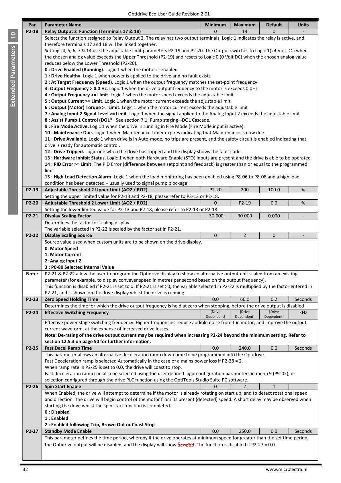
Relay Output 2 Function (Terminals 17 & 18)
Selects the function assigned to Relay Output 2. The relay has two output terminals, Logic 1 indicates the relay is active, and
therefore terminals 17 and 18 will be linked together.
Settings 4, 5, 6, 7 & 14 use the adjustable limit parameters P2-19 and P2-20. The Output switches to Logic 1(24 Volt DC) when
the chosen analog value exceeds the Upper Threshold (P2-19) and resets to Logic 0 (0 Volt DC) when the chosen analog value
reduces below the Lower Threshold (P2-20).
0 : Drive Enabled (Running). Logic 1 when the motor is enabled
1 : Drive Healthy. Logic 1 when power is applied to the drive and no fault exists
2 : At Target Frequency (Speed). Logic 1 when the output frequency matches the set-point frequency
3: Output Frequency > 0.0 Hz. Logic 1 when the drive output frequency to the motor is exceeds 0.0Hz
4 : Output Frequency >= Limit. Logic 1 when the motor speed exceeds the adjustable limit
5 : Output Current >= Limit. Logic 1 when the motor current exceeds the adjustable limit
6 : Output (Motor) Torque >= Limit. Logic 1 when the motor current exceeds the adjustable limit
7 : Analog Input 2 Signal Level >= Limit. Logic 1 when the signal applied to the Analog Input 2 exceeds the adjustable limit
8 : Assist Pump 1 Control (DOL* . See section 7.1, Pump staging –DOL Cascade.
9 : Fire Mode Active. Logic 1 when the drive in running in Fire Mode (Fire Mode input is active).
10 : Maintenance Due. Logic 1 when Maintenance Timer expires indicating that Maintenance is now due.
11 : Drive Available. Logic 1 when drive is in Auto-mode, no trips are present, and the safety circuit is enabled indicating that
drive is ready for automatic control.
12 : Drive Tripped. Logic one when the drive has tripped and the display shows the fault code.
13 : Hardware Inhibit Status. Logic 1 when both Hardware Enable (STO) inputs are present and the drive is able to be operated
14 : PID Error >= Limit. The PID Error (difference between setpoint and feedback) is greater than or equal to the programmed
limit
15 : High Load Detection Alarm. Logic 1 when the load monitoring has been enabled using P8-06 to P8-08 and a high load
condition has been detected – usually used to signal pump blockage
Adjustable Threshold 2 Upper Limit (AO2 / RO2)
Setting the upper limited value for P2-13 and P2-18, please refer to P2-13 or P2-18.
Adjustable Threshold 2 Lower Limit (AO2 / RO2)
Setting the lower limited value for P2-13 and P2-18, please refer to P2-13 or P2-18.
Determines the factor for scaling display.
The variable selected in P2-22 is scaled by the factor set in P2-21.
Source value used when custom units are to be shown on the drive display.
0: Motor Speed
1: Motor Current
2: Analog Input 2
3 : P0-80 Selected Internal Value
P2-21 & P2-22 allow the user to program the Optidrive display to show an alternative output unit scaled from an existing
parameter (for example, to display conveyer speed in metres per second based on the output frequency).
This function is disabled if P2-21 is set to 0. If P2-21 is set >0, the variable selected in P2-22 is multiplied by the factor entered in
P2-21, and is shown on the drive display whilst the drive is running.
Determines the time for which the drive output frequency is held at zero when stopping, before the drive output is disabled
Effective Switching Frequency
Effective power stage switching frequency. Higher frequencies reduce audible noise from the motor, and improve the output
current waveform, at the expense of increased drive losses.
Note: De-rating of the drive output current may be required when increasing P2-24 beyond the minimum setting. Refer to
section 12.5.3 on page 50 for further information.
This parameter allows an alternative deceleration ramp down time to be programmed into the Optidrive.
Fast Deceleration ramp is selected Automatically in the case of a mains power loss if P2-38 = 2.
When ramp rate in P2-25 is set to 0.0, the drive will coast to stop.
Fast deceleration ramp can also be selected using the user defined logic configuration parameters in menu 9 (P9-02), or
selection configured through the drive PLC function using the OptiTools Studio Suite PC software.
When Enabled, the drive will attempt to determine if the motor is already rotating on start up, and to detect rotational speed
and direction. The drive will begin control of the motor from its present (detected) speed. A short delay may be observed when
starting the drive whilst the spin start function is completed.
0 : Disabled
1 : Enabled
2 : Enabled following Trip, Brown Out or Coast Stop
This parameter defines the time period, whereby if the drive operates at minimum speed for greater than the set time period,
the Optidrive output will be disabled, and the display will show . The function is disabled if P2-27 = 0.0.

 Loading...


