4.8.6. “STO” Function response time
The total response time is the time from a safety related event occurring to the components (sum of) within the system responding and
becoming safe. (Stop Category 0 in accordance with IEC 60204-1)
The,response,time,from,the,“STO”,inputs,being,de-energised to the output of the drive being in a state that will not produce
torque in the motor,(“STO”,active),is,less,than,1ms
The,response,time,from,the,“STO”,inputs,being,de-energised,to,the,“STO”,monitoring,status,changing,state,is,less,than,20ms
The response time from the drive sensing a fault in the STO circuit to the drive displaying the fault on the display/Digital output
showing drive not healthy is less than 20ms.
4.8.7. “STO“ Electrical Installation
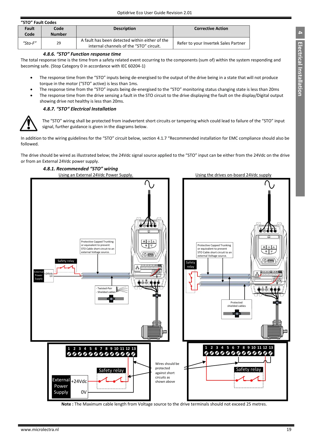
The,“STO”,wiring,shall,be,protected,from,inadvertent,short,circuits,or,tampering,which,could,lead,to,failure,of,the,“STO”,input
signal, further guidance is given in the diagrams below.
In,addition,to,the,wiring,guidelines,for,the,“STO”,circuit,below,section,4.1.7 “Recommended,installation for EMC compliance should also be
followed.
The,drive,should,be,wired,as,illustrated,below,the,24Vdc,signal,source,applied,to,the,“STO”,input,can,be,either,from,the 24Vdc on the drive
or from an External 24Vdc power supply.
4.8.1. Recommended “STO” wiring
Using an External 24Vdc Power Supply. Using the drives on-board 24Vdc supply

 Loading...


