60 | Fieldbus Guide | Version 1.02 www.invertekdrives.com
11
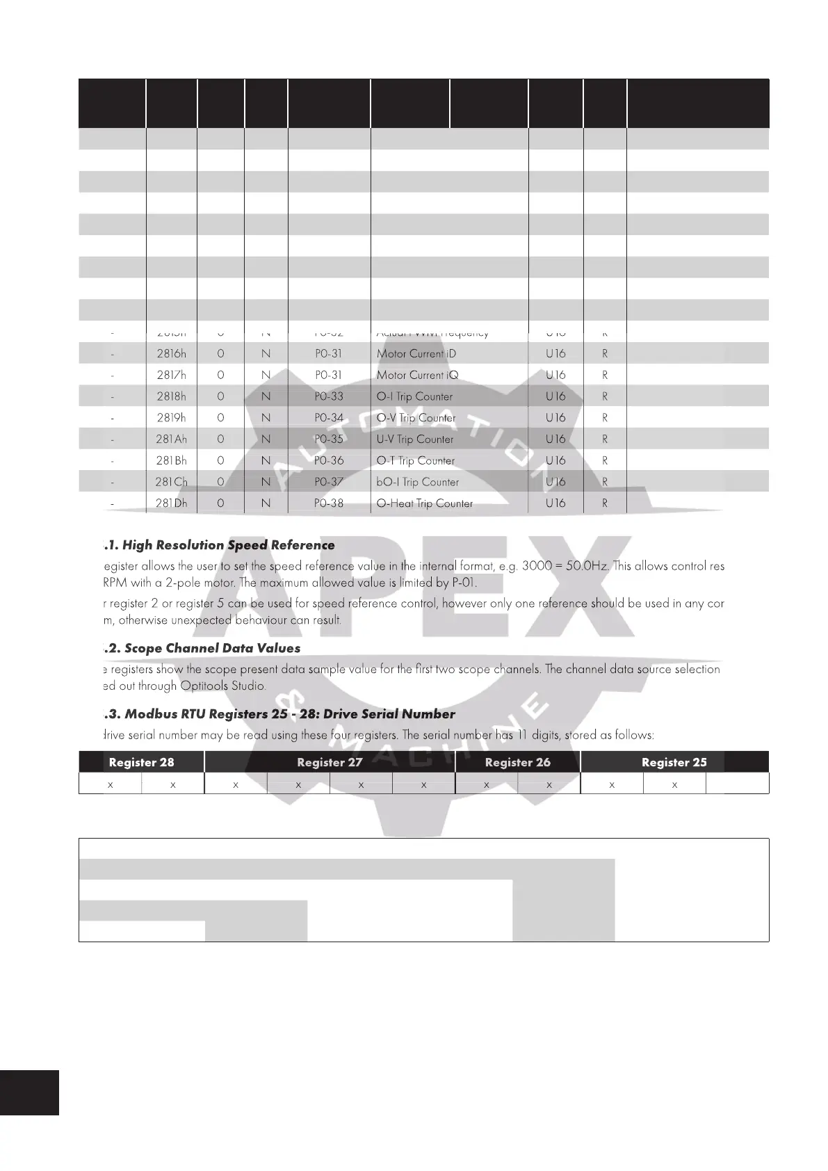
Additional Status Registers
Modbus
RTU
Register
CAN
Open
Index
Sub
Index
PDO
Map
Parameter
Number
Upper byte Lower Byte Format Type Scaling
- 280Ch 0 N P0-18 DC Ripple Log 1 U16 R 1 = 1 Volt
- 280Dh 0 N P0-18 DC Ripple Log 2 U16 R 1 = 1 Volt
280Eh 0 N P0-18 DC Ripple Log 3 U16 R 1 = 1 Volt
- 280Fh 0 N P0-18 DC Ripple Log 4 U16 R 1 = 1 Volt
- 2810h 0 N P0-18 DC Ripple Log 5 U16 R 1 = 1 Volt
- 2811h 0 N P0-18 DC Ripple Log 6 U16 R 1 = 1 Volt
- 2812h 0 N P0-18 DC Ripple Log 7 U16 R 1 = 1 Volt
- 2813h 0 N P0-18 DC Ripple Log 8 U16 R 1 = 1 Volt
- 2814h 0 N P0-25 Estimated Rotor Speed S 16 R
- 2815h 0 N P0-32 Actual PWM Frequency U16 R
- 2816h 0 N P0-31 Motor Current iD U16 R
- 2817h 0 N P0-31 Motor Current iQ U16 R
- 2818h 0 N P0-33 O-I Trip Counter U 16 R
- 2819h 0 N P0-34 O-V Trip Counter U 16 R
- 281Ah 0 N P0-35 U-V Trip Counter U16 R
- 281Bh 0 N P0-36 O-T Trip Counter U16 R
- 281Ch 0 N P0-37 bO-I Trip Counter U16 R
- 281Dh 0 N P0-38 O-Heat Trip Counter U16 R
11.4.1. High Resolution Speed Reference
This register allows the user to set the speed reference value in the internal format, e.g. 3000 = 50.0Hz. This allows control resolution
to 1 RPM with a 2-pole motor. The maximum allowed value is limited by P-01.
Either register 2 or register 5 can be used for speed reference control, however only one reference should be used in any control
system, otherwise unexpected behaviour can result.
11.4.2. Scope Channel Data Values
These registers show the scope present data sample value for the first two scope channels. The channel data source selection is
carried out through Optitools Studio.
11.4.3. Modbus RTU Registers 25 - 28: Drive Serial Number
The drive serial number may be read using these four registers. The serial number has 11 digits, stored as follows:
Register 28 Register 27 Register 26 Register 25
xxxxxxxxxxx
e.g.
Register 25 1
Register 26 1
Register 27 8745
Register 28 57
Drive Serial Number 5 7 8 7 4 5 0 1 0 0 1
11.4.4. Parameter Checksum Modbus Register 46
A checksum is calculated based on the present value of all user adjustable parameters and stored in Modbus Register 46. This may
be read to determine if parameter settings have been adjusted.
- 2815h 0 N P0-32 Actual PWM Frequency
- 2815h 0 N P0-32 Actual PWM Frequency
- 2815h 0 N P0-32 Actual PWM Frequency
- 2815h 0 N P0-32 Actual PWM Frequency
- 2815h 0 N P0-32 Actual PWM Frequency
- 2815h 0 N P0-32 Actual PWM Frequency
- 2816h 0 N P0-31 Motor Current iD
- 2816h 0 N P0-31 Motor Current iD
- 2816h 0 N P0-31 Motor Current iD
- 2816h 0 N P0-31 Motor Current iD
- 2816h 0 N P0-31 Motor Current iD
- 2816h 0 N P0-31 Motor Current iD
- 2817h 0 N P0-31 Motor Current iQ
- 2817h 0 N P0-31 Motor Current iQ
- 2817h 0 N P0-31 Motor Current iQ
- 2817h 0 N P0-31 Motor Current iQ
- 2817h 0 N P0-31 Motor Current iQ
- 2817h 0 N P0-31 Motor Current iQ
- 2818h 0 N P0-33 O-I Trip Counter
- 2818h 0 N P0-33 O-I Trip Counter
- 2818h 0 N P0-33 O-I Trip Counter
- 2818h 0 N P0-33 O-I Trip Counter
- 2818h 0 N P0-33 O-I Trip Counter
- 2818h 0 N P0-33 O-I Trip Counter
- 2819h 0 N P0-34 O-V Trip Counter
- 2819h 0 N P0-34 O-V Trip Counter
- 2819h 0 N P0-34 O-V Trip Counter
- 2819h 0 N P0-34 O-V Trip Counter
- 2819h 0 N P0-34 O-V Trip Counter
- 2819h 0 N P0-34 O-V Trip Counter
- 281Ah 0 N P0-35 U-V Trip Counter
- 281Ah 0 N P0-35 U-V Trip Counter
- 281Ah 0 N P0-35 U-V Trip Counter
- 281Ah 0 N P0-35 U-V Trip Counter
- 281Ah 0 N P0-35 U-V Trip Counter
- 281Ah 0 N P0-35 U-V Trip Counter
- 281Bh 0 N P0-36 O-T Trip Counter
- 281Bh 0 N P0-36 O-T Trip Counter
- 281Bh 0 N P0-36 O-T Trip Counter
- 281Bh 0 N P0-36 O-T Trip Counter
- 281Bh 0 N P0-36 O-T Trip Counter
- 281Bh 0 N P0-36 O-T Trip Counter
- 281Ch 0 N P0-37 bO-I Trip Counter
- 281Ch 0 N P0-37 bO-I Trip Counter
- 281Ch 0 N P0-37 bO-I Trip Counter
- 281Ch 0 N P0-37 bO-I Trip Counter
- 281Ch 0 N P0-37 bO-I Trip Counter
- 281Ch 0 N P0-37 bO-I Trip Counter
- 281Dh 0 N P0-38 O-Heat Trip Counter
- 281Dh 0 N P0-38 O-Heat Trip Counter
- 281Dh 0 N P0-38 O-Heat Trip Counter
- 281Dh 0 N P0-38 O-Heat Trip Counter
- 281Dh 0 N P0-38 O-Heat Trip Counter
- 281Dh 0 N P0-38 O-Heat Trip Counter
11.4.1. High Resolution Speed Reference
This register allows the user to set the speed reference value in the internal format, e.g. 3000 = 50.0Hz. This allows control resolution
to 1 RPM with a 2-pole motor. The maximum allowed value is limited by P-01.
Either register 2 or register 5 can be used for speed reference control, however only one reference should be used in any control
system, otherwise unexpected behaviour can result.
11.4.2. Scope Channel Data Values
These registers show the scope present data sample value for the first two scope channels. The channel data source selection is
carried out through Optitools Studio.
11.4.3. Modbus RTU Registers 25 - 28: Drive Serial Number
The drive serial number may be read using these four registers. The serial number has 11 digits, stored as follows:

 Loading...
