Version 1.02 | Fieldbus Guide | 9www.invertekdrives.com
4
Modbus RTU
4.2.3. Optidrive Compact 2 Basic
Suitable Motor Types
Optidrive Compact 2 Basic drives also include the RJ45 connector with the same layout as Optidrive E3 units shown above.
Additionally, the Modbus RTU interface is also present on terminals as follows:
Terminal 7: 0V
Terminal 10: Modbus RTU +
Terminal 11: Modbus RTU -
15
1
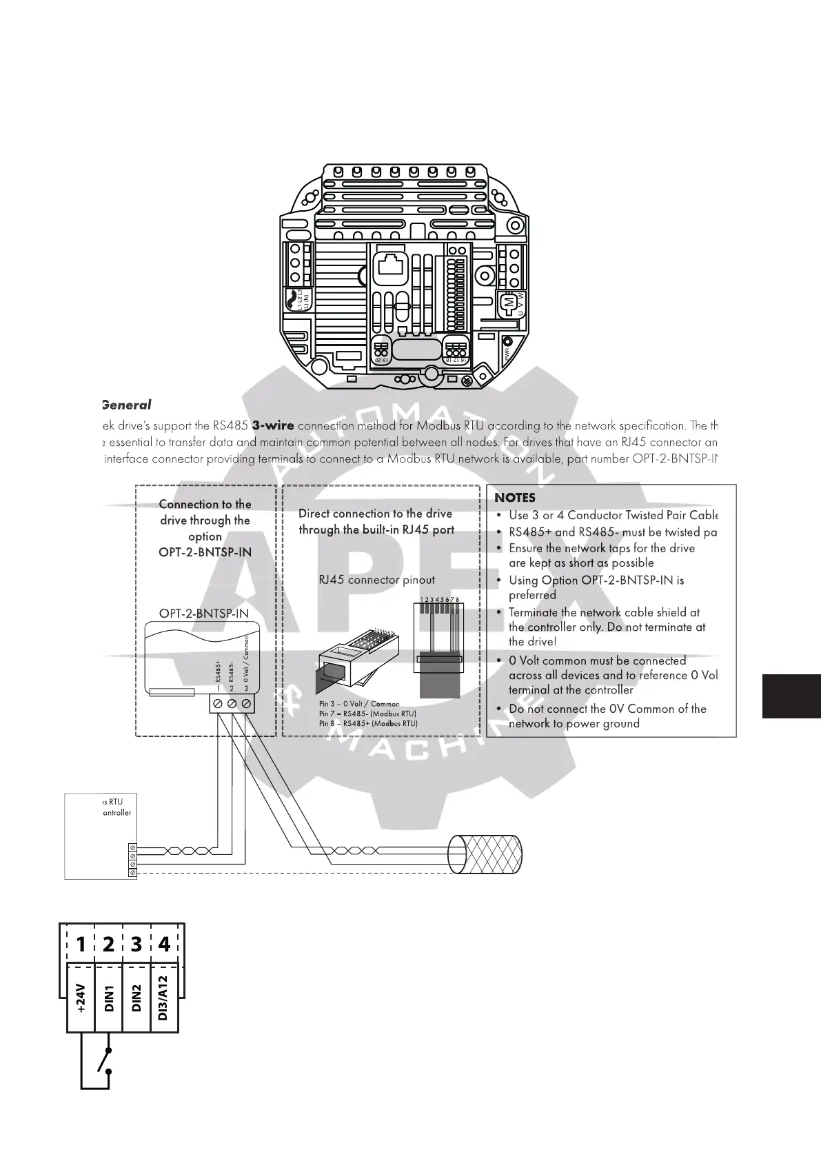
4.2.4. General
All Invertek drive’s support the RS485 3-wire connection method for Modbus RTU according to the network specification. The three
wires are essential to transfer data and maintain common potential between all nodes. For drives that have an RJ45 connector an
optional interface connector providing terminals to connect to a Modbus RTU network is available, part number OPT-2-BNTSP-IN.
Modbus RTU
RS485 Controller
RS485+
RS485-
0 Volt / Common
Ground
NOTES
• Use 3 or 4 Conductor Twisted Pair Cable
•RS485+ and RS485- must be twisted pair
• Ensure the network taps for the drive
are kept as short as possible
• Using Option OPT-2-BNTSP-IN is
preferred
•Terminate the network cable shield at
the controller only. Do not terminate at
the drive!
•0Volt common must be connected
across all devices and to reference 0 Volt
terminal at the controller
•Do not connect the 0V Common of the
network to power ground
RS485+
RS485-
0 Volt / Common
Shield
OPT-2-BNTSP-IN
OPT-2-BNTSP-IN
12 3
RS485+
0 Volt / Common
Connection to the
drive through the
option
OPT-2-BNTSP-IN
RS485-
Pin 3 –0 Volt / Common
Pin 7 – RS485- (Modbus RTU)
Pin 8 – RS485+ (Modbus RTU)
RJ45 connector pinout
Direct connection to the drive
through the built-in RJ45 port
1 2 3 4 5 6 7 8
1
2
3
4
5
6
7
8
4.2.5. Control Terminal Connection
All Invertek drive’s support the RS485
connection method for Modbus RTU according to the network specification. The three
wires are essential to transfer data and maintain common potential between all nodes. For drives that have an RJ45 connector an
optional interface connector providing terminals to connect to a Modbus RTU network is available, part number OPT-2-BNTSP-IN.
S485+ and RS485- must be twis
• Using Option OPT-2-BNTSP-IN is
o not connect the 0V Common of the
ct connection to the drive

 Loading...
