DA180 series basic AC servo drive Commissioning
-234-
P2.10
P2.11
P2.02
P2.07
P1.29
P1.30
P2.04
P1.31
P1.32
P2.03
P2.00
P2.01
P1.33
P1.34
P2.09
P2.08
P2.12
P2.13
P0.06
P0.07
P0.08
P2.42
P2.43
P1.23
P1.24
P1.25
P1.26
P1.27
P1.28
P1.19 P1.20
P2.20
P2.22
P2.71
P2.72
P2.73
P2.24
P2.25
P2.23 P2.26
P0.09
P0.10
P0.11
P4.53
P4.51
P4.52
P4.67
P4.60
P4.61
P4.62
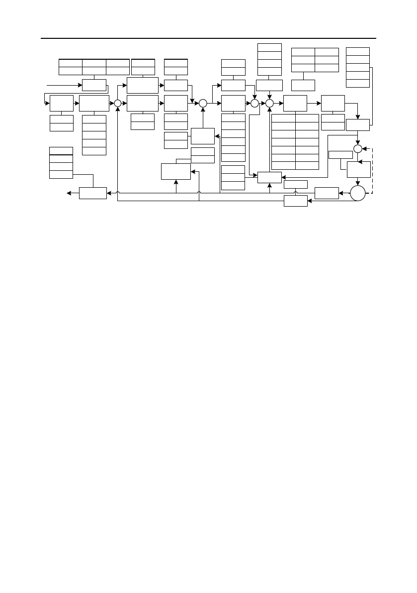
Position command
P0.27
P0.28
P0.29
P0.33
P0.34
P1.35
P1.36
P0.25
P0.26P0.22
P1.37
P1.38
P1.39
P2.70
P2.41
Electronic
gear
Speed
feedforward
Torque
feedforward
Friction
compensation
Gain
switching
Position
command
vibration control
Position
smoothing
filter
Position
controller
Torque filterNotch filter
Speed
controller
Torque limit
Frequency-
division output
Encoder
Motor
Grating ruler
Disturbance
control
Current
controller
Speed
detection
filter
Hybrid-control
deviation
calculation
P1.02
P1.01
P2.06
P2.05
Frequency-
division ratio of
grating ruler
P4.60
P4.61
Frequency-
division ratio of
grating ruler
P4.60
P4.61
The common procedure for adjusting parameters in position mode is as follows:
1. Restore default settings.
For details, see section 5.2.5.3 "Factory parameter restoring".
2. Adjust the position loop gain.
If the servo motor runs with default settings but the system vibrates with buzzes, decrease the
position loop gain (that is, P2.02 or P2.07) or increase it when the system rigidity is low.
3. Adjust the position smoothing filter.
In position control, if the input frequency changes of position pulse commands are noticeable, huge
surges may be caused. You need to adjust the P0.33 [Position command smooth filter time] or P0.34
[Position command FIR filter time].
4. Adjust the electronic gear.
If the pulse generation device is limited on the pulse sending frequency or the sending frequency
does not meet mechanical requirements, you can change the pulse input frequency by adjusting
P0.22 [Pulses per motor resolution] or electronic gear ratio parameters P0.25, P0.26, P0.27, P0.28,
and P0.29, so as to meet position control requirements.
5. Adjust the position feed-forward.
If the residual pulses are great or no-deviation tracking is required, you can adjust the speed
feed-forward gain parameter P2.10 and speed feed-forward filtering parameter P2.11 to improve
position tracking performance. However, if the speed feed-forward gain is too large, the system may
vibrate.
6. Set the frequency division for feedback pulse output.
If feedback pulses need to be output, you can set the frequency-division output coefficient parameters
P0.06 and P0.07 to change the pulse output frequency.
 Loading...
