DA180 series basic AC servo drive Control modes
-50-
4.5 Wiring description for CN1
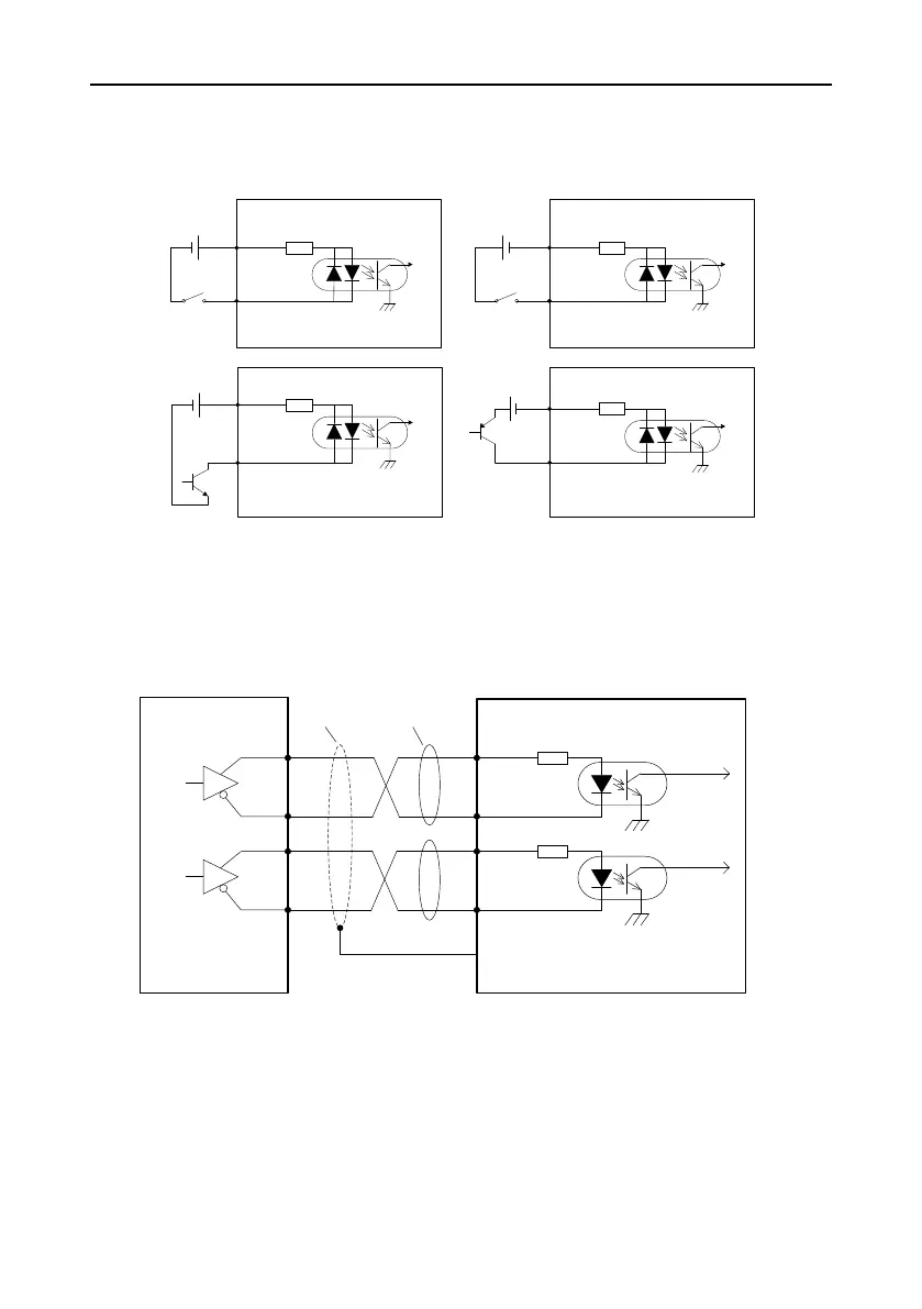
4.5.1 Digital input circuit wiring
Drive side
2 COM+
DC12~24V
- +
16 DI1
Drive side
2 COM+
DC12~24V
- +
16 DI1
Drive side
2 COM+
16 DI1
DC12~24V
+ -
Active low Active high
PNP
NPN
Drive side
2 COM+
16 DI1
DC12~24V
+ -
The digital input power is user provided.
As shown in the figure, the digital input circuit supports mechanical switch connection and open
collector connection using NPN or PNP triodes, disallowing the hybrid of the two types.
4.5.2 Pulse input circuit wiring
Method 1: Differential connection
Control module
side
Drive side
23 PULS+
24 PULS-
33 SIGN-
FG
PULS
SIGN
32 SIGN+
Shielded
cable
Twisted
pair
The differential pulse input signal voltage is ±5V and maximum frequency is 4 MHz.
This signal transmission method is recommended since it has excellent anti-nose capability.
 Loading...
