Frequency
divider
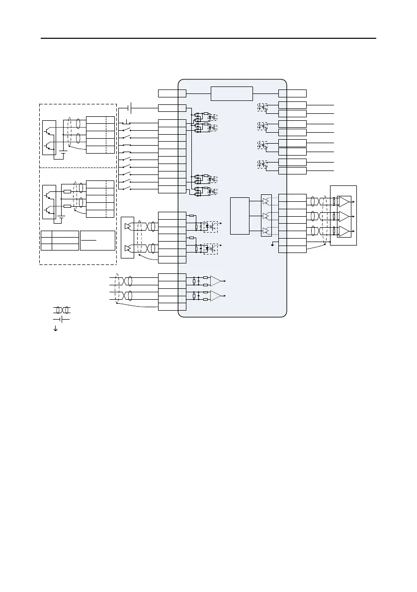
External
controller
Note: user-provided
DC12~24V
- +
DI common terminal
EMG 39
SON 16
ZRS 37
POT 3
NOT 4
CLA 10
SC1 34
SC2 17
RPC 18
PLL 22
Command pulse
inhibiting
Residual pulse clearing
Electronic gear
selection 2
Electronic gear
selection 1
Alarm clearing
Servo enabling
Zero speed clamp
COM+ 2
44 OA+
43 OA-
41 OB+
42 OB-
FG
AD1 20
GND 6
AD2 7
GND 6
FG
AM26LS32
or equivalent chip
Differential command
pulse input (max.
4Mpps)
28 OZ+
27 OZ-
6 GND GND
CN1
Analog input 1
Analog input 2
Analog signal GND
Analog signal GND
Max load
capability for
each output
terminal:
DC30V, 50mA
15 ALM+
19 ALM-
Fault alarm output
14 RDY+
5 RDY-
Servo being ready
29 ZSO+
35 ZSO-
Zero speed output
11 PLR+
8 PLR-
Positioning
completion
PULS+ 23
PULS- 24
SIGN- 33
FG
SIGN+ 32
24V power, with a built-in
current limit resistor
12–24V power, with an
external current limit resistor
V
DC
(12~24V)
OCP 38
PULS- 24
SIGN- 33
FG
OCS 31
V
DC
(24V)
R
R
V
DC
-1.5
R+68
10mA
Note: The max. open collector
input is 200kpps.
12V 1k,1/4W
24V 2k,1/3W
V
DC
Resistor reference
+
-
+
-
PULS+ 23
PULS- 24
OCP 38
2kΩ
SIGN+ 32
SIGN- 33
OCS 31
2kΩ
FG
12V 40
Internal DC12V power
Note: Capacity 100mA
12 GND
Emergency stop
Forward drive disabling
Reverse drive disabling
Position control mode
1. ( ) is shielded twisted cable.
2. ( ) is user-provided power.
3. ( ) is GND, corresponding to pin 6/12.
Note:
 Loading...
