DA180 series basic AC servo drive Control modes
-52-
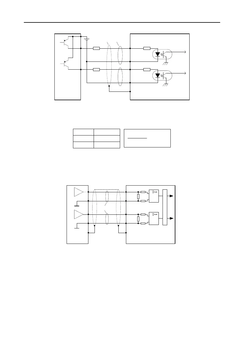
Control module using PNP triodes with common anode:
Control module
side
Drive side
23 PULS+
24 PULS-
33 SIGN-
FG
Y1
Y0
PULSE
SIGN
32 SIGN+
+
-
Current limit
resistor R
Current limit
resistor R
Shielded
cable
Twisted
pair
The maximum input pulse frequency is 200 kHz. You can use the 12V power (able to provide only
100mA current) equipped with the drive or the 12–24V power provided by yourself. You need to
connect current limit resistors externally. Select current limit resistors according to the following:
V
DC
-1.5
R+68
10(mA)
V
DC
R specs
12V 1kΩ,1/4W
24V 2kΩ,1/3W
For each method, the shielded twisted pair is required, and you are recommended that the pair cable
length be less than 3 meters.
4.5.3 Analog input circuit wiring
0
0
0
20 AD1
6 GND
7 AD2
A
D
C
FG
Connect the shielded
cable according to
device requirements
Twisted
pair
6 GND
0
0
0
Drive side
Control
module side
There are two channels of analog input circuit, AD1 and AD2, both of which are accurate to 12 bits.
The input impedance is 13kΩ. The input voltage ranges from -10V to +10V. If the voltage is ±11V less
or greater, the circuit may be damaged.
 Loading...
