DA180 series basic AC servo drive Operating and running
-58-
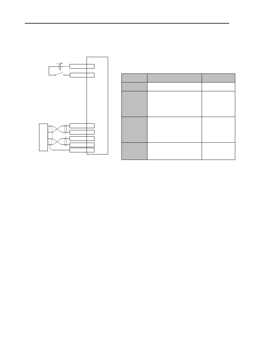
5.1.3 Running in position control mode
Simplified wiring
SON 16
DC
12~24V
PULS+ 23
PULS- 24
SIGN+ 32
SIGN- 33
FG
Upper
pulse
genera-
tor
Servo drive
CN1
COM+ 2
Procedure
1. Complete the connect between the servo drive and servo motor.
2. Set P0.03 to 0, which indicates the position control mode.
3. Check the pulse output mode of the upper controller. Adjust P0.23 to keep the pulse mode the
same as that of the upper controller. See the description for P0.23 for details.
4. Switch off and re-switch on the main power for the settings of P0.03 and P0.23 to take effect.
5. Connect the plug of CN1 to the drive, switch on the power, and ensure that SON and 24V GND
are connected. The motor enters the locking state.
6. Wait the upper controller to send the low frequency pulse command. The motor rotates at a low
speed.
7. Check whether the motor rotation direction is consistent with the design. If not, change the
direction through the upper controller or perform the reverse operation through P0.24.
8. Ensure the input pulse count complies with the design. You can set P0.22 [Pulses per motor
resolution] or the electronic gear ratio parameters P0.25 and P0.26 to divide or multiply frequency.
See the description for P0.22, P0.25 and P0.26 for details.
Pulses per motor
resolution
Depends on
the actual
situation.
Depends on
the actual
situation.
Reverse pulse input
direction
 Loading...
