EasyManua.ls Logo

INVT DA180-S4R5SG0

INVT DA180-S4R5SG0
316 pages
To Next Page IconTo Next Page
To Previous Page IconTo Previous Page
Loading...
DA180 series basic AC servo drive Control modes
-39-
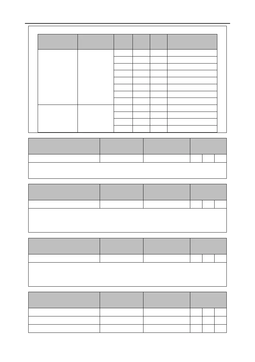
Signals of selecting from internal-speed commands 1 to 8 or from internal speed limits 1 to 4.
Control mode
Setting of P0.40
SPD3
SPD2
SPD1
Associated parameter
and setting
Speed mode
0
0
0
0
P0.46, internal speed 1
0
0
1
P0.47, internal speed 2
0
1
0
P0.48, internal speed 3
0
1
1
P0.49, internal speed 4
1
0
0
P0.50, internal speed 5
1
0
1
P0.51, internal speed 6
1
1
0
P0.52, internal speed 7
1
1
1
P0.53, internal speed 8
Torque mode
0
0
0
0
P0.46, speed limit 1
0
0
1
P0.47, speed limit 2
0
1
0
P0.48, speed limit 3
0
1
1
P0.49, speed limit 4
Signal
Symbol
Function
Applicable
mode
Zero-point clamping
ZRS
0x0D
S
T
Signal of controlling zero-point clamping. The detailed action is associated with the setting of
P0.58 [Zero-point clamping mode]. For details, see the description for P0.58.
Signal
Symbol
Function
Applicable
mode
Speed command sign
S-SIGN
0x0E
S
Signal of selecting the sign for speed command input in speed mode.
If P0.41 [Speed command direction setting] is set to 1, this digital input takes effect. If P0.41 is set
to 0, it does not take effect.
Signal
Symbol
Function
Applicable
mode
Torque command sign
T-SIGN
0x0F
T
Signal of selecting the sign for torque command input in torque control mode.
If P0.61 [Torque command direction setting] is set to 1, this digital input takes effect, If P0.61 is
set to 0, it does not take effect.
Signal
Symbol
Function
Applicable
mode
Internal position command 1
POS1
0x10
P
Internal position command 2
POS2
0x11
P
Internal position command 3
POS3
0x12
P

Table of Contents

Related product manuals