Goodrive300-19 series open loop vector inverter special for hosit Basic operation instruction
-170-
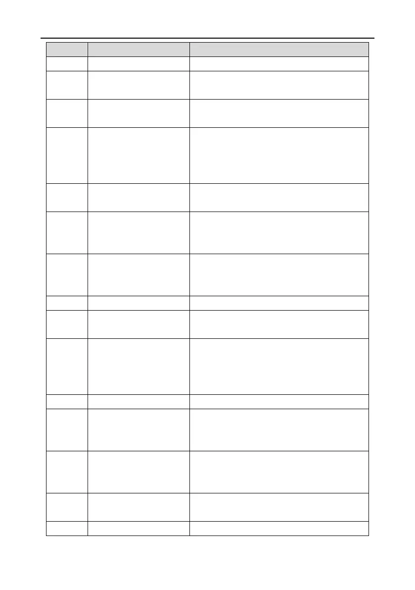
given frequency of the inverter is 0 at the same time.
Upper limit frequency arrival
Output ON signal when the running frequency of the
inverter is the upper limit frequency.
Lower limit frequency arrival
Output ON signal when the running frequency of the
inverter is the lower limit frequency.
When the main circuit and the control circuit is
established and the protection function of the inverter
is not active. The inverter is in the running state and it
will output ON signal.
Output ON signal when the inverter is in the
pre-exciting state.
Output ON signal if the inverter is beyond the
pre-alarm point. Refer to P11.08~P11.10 for the
detailed instruction.
Output ON signal if the inverter is beyond the
pre-alarm point. Refer to P11.11~P11.12 for the
detailed instruction.
Output ON signal if the accumulative running time of
the inverter exceeds the setting time by P08.27.
Modbus communication
virtual terminal output
Output corresponding signal according to the setting
value of Modbus. Output ON signal if the setting
value is 1 and output OFF signal if the setting value
is 0.
After P19.01 selects the contactor is controlled by the
inverter, output contactor control signal (ON: close,
OFF: open).
After P19.01 selects the brake is controlled by the
inverter, output brake control signal (ON: switch off,
OFF: switch on).
Output ON signal after switching-off frequency
arrives and torque verification succeeds at starting.
Output ON signal after the frequency is lower than

 Loading...


