Goodrive300-19 series open loop vector inverter special for hosit Basic operation instruction
-184-
Brake and contactor control
selection
Brake is controlled by inverter
7.16.3 Remote control mode
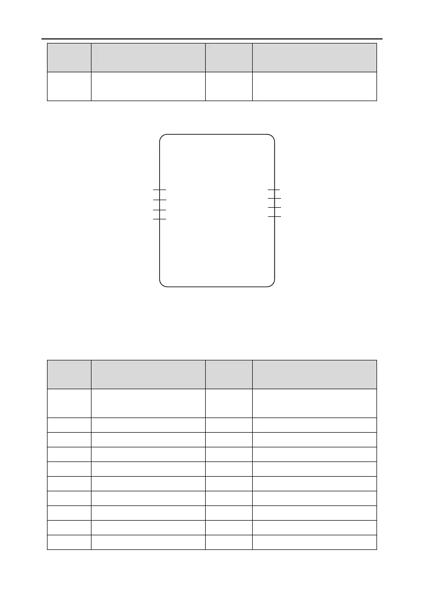
The wiring diagram of remote control mode is as follows:
GD300-19 inverter
FWD running
S1
Frequency reference
AI1
REV running
S2
Fault reset S3
RO1
RO2
Fault output
AO1
Running frequency
AO2
Current output
Brake output
The mode is used in the case where the joystick is connected to the external wireless controller or
PLC. Set P19.00 to “2: Remote control mode”.
The speed is given by AI1 and the forward and reverse direction signals of the hoist are given by S1
and S2. For remote control mode, joystick zero position detection is invalid.
The parameters of remote control mode are as follows:
Terminal running command
channel (LED flickering)
S1 terminal function selection
Forward rotation operation (FWD)
S2 terminal function selection
Reverse rotation operation (REV)
S3 terminal function selection
Brake and contactor control
Brake is controlled by inverter

 Loading...


