Goodrive300-19 series open loop vector inverter special for hosit Basic operation instruction
-183-
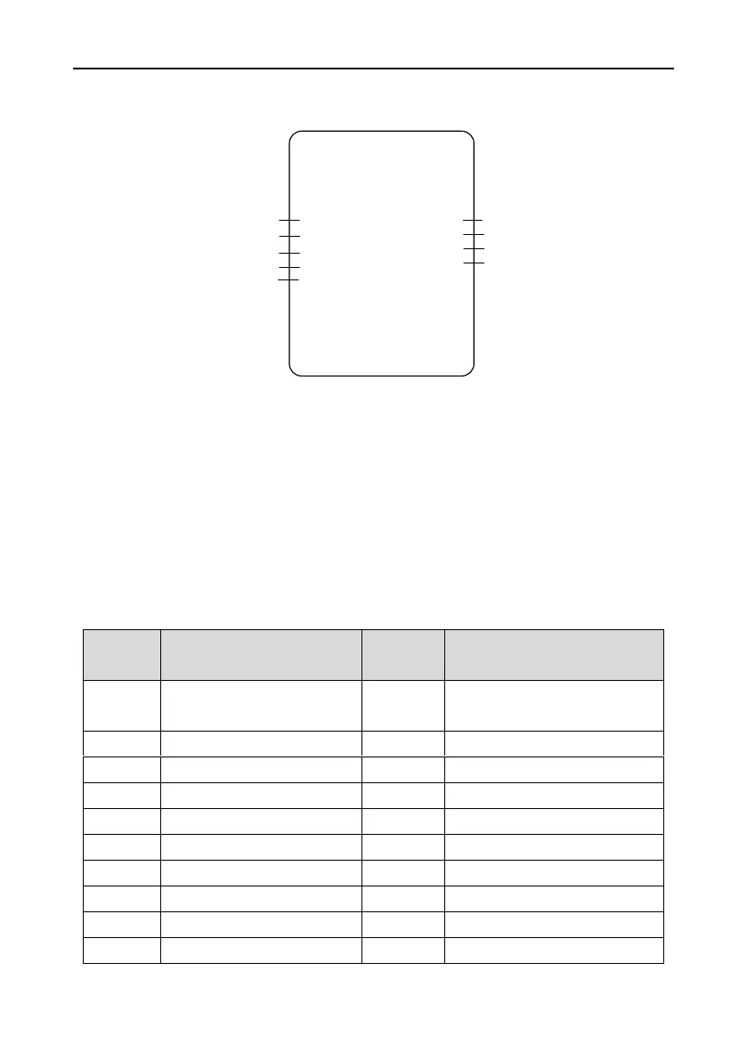
7.16.2 Joystick mode
The wiring diagram of joystick mode is as follows:
GD300-19 inverter
FWD running
S1
Frequency reference
AI1
REV running
S2
Fault reset
S3
RO1
Brake output
RO2
Fault output
AO1
Running
frequency
AO2
Output current
Zero position signal
S4
The joystick mode is used in the case where the joystick is connected directly to inverter analog input
I/O. Set P19.00 to “1: Joystick mode”.
The speed is given by AI1 and the forward and reverse direction signals of the hoist are given by S1
and S2. The mode can select joystick zero postion detection. After stop, the inverter will not be
allowed to restart until the joystick returns to zero position (neutral position) and the time exceeds the
defined time in P19.28. When P19.27=1, detection enabling at joystick zero position is valid.
When the joystick returns to zero postion, if the detected speed reference AI1 by the inverter is larger
than 1V, it may be speed reference deviation fault. The keypad will display the information of analog
speed reference deviation fault.
The parameters of joystick mode are as follows:
Terminal running command
channel (LED flickering)
S1 terminal function selection
Forward rotation operation (FWD)
S2 terminal function selection
Reverse rotation operation (REV)
S3 terminal function selection
S4 terminal function selection
Joystick zero position signal

 Loading...


