Goodrive35 Series Closed-loop Vector Control VFD Basic operation instruction
144
Suggestions:
1. For the load of constant torque, such as the conveyor belt which runs linearly. It is properly to select
linear V/F curve because it needs constant torque.
2. For the load of decreasing torque, such as fans and water pumps, it is properly to select
corresponding 1.3th, 1.7th or 2th power of V/F curve because the actual torque is 2-squared or
3-squared of the rotating speed.
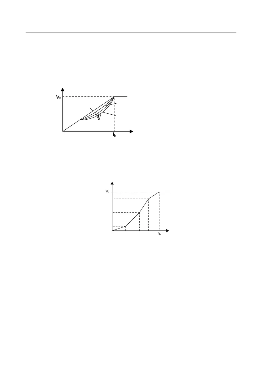
Output voltage
Output frequency
Linear type
Square type
Torque step-down V/F curve (1.3 order)
Torque step-down V/F curve (1.7 order)
Torque step-down V/F curve (2.0 order)
Goodrive35 series VFDs provide multi-dots V/F curve, the user can change the output V/F curve by
setting the voltage and frequency of three middle dots. The whole curve is consisted of 5 dots. The
starting dot is (0 Hz, 0 V), and the ending dot is (the basic frequency of the motor, the rated voltage
of the motor). During the setting processing: 0≤f
1
≤f
2
≤f
3
≤the basic frequency of the motor; 0≤ V
1
≤ V
2
≤
V
3
≤the rated voltage of the motor.
Output voltage
Output
frequency
(Hz)
V1
V2
V3
f1 f2 f3
100.0%
Goodrive35 series VFDs provide special function code for SVPWM control mode which can improve
the performance of SVPWM control by means of setting.
1. Torque boost
Torque boost function can effectively compensate for the performance of low speed torque during
SVPWM control. Automatic torque boost has been set by default to enable the VFD to adjust the
torque boost value based on the actual load conditions.
Note:
The torque boost takes effect only when the frequency is under the cap frequency of the boost. If the
torque boost is too big, low frequency vibration or overcurrent fault may occur to the motor. If such
situation occurs, lower the torque boost value..

 Loading...