Goodrive35 Series Closed-loop Vector Control VFD Basic operation instruction
194
be adjusted. If the pulse train is selected to control the speed, set P21.00=0000, P00.06 or
P00.07=12, AB pulse train, then the acceleration and deceleration time depend on the time of the
VFD and the parameter setting is determined by P21. In speed control mode, set the filter time of AB
pulse by P21.29.
(8)The input frequency of the pulse train is the same as the feedback frequency of the encoder pulse.
The relationship between them can be changed by modifying P21.11 and P21.12.
(9)When run command or servo enable is valid by setting P21.00 or terminal function 63, the VFD will
run into the pulse string servo mode.
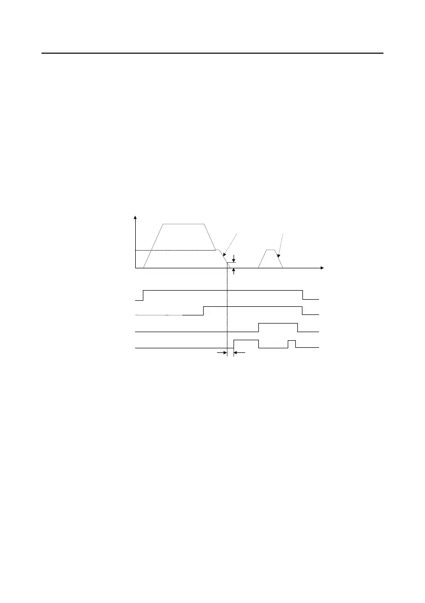
4. Debugging steps of spindle positioning
The spindle positioning is the function of stopping such as zeroing and scaling on the basis of
closed-loop vector control.
Frequency
Time
Running
command
Return
command
Zeroing
terminal 1
P22.01
Position
finished signal
P21.10
P21.09
P22.02
ON
ON
ON
ON
ON
P21.25
P21.25
The steps of (1)–(4) are the same as the 4 steps in close-loop vector control mode. The function of
spindle positioning is available in the position control mode and speed control mode.
(5) Set P22.00.bit0=1 and P22.00.bit1. If the system applies encoder to detect the speed, set
P22.00.bit1=0, and if the system applies the photoelectric switch to detect the speed, set
P22.00.bit1=1; set P22.00.bit2, P22.00.bit3 and P22.00.bit7
(6)Spindle zeroing
a) Set P22.00.bit4 to select the positioning direction.
b) There are 4 zero positions in P22 group. Set P05 to select the zeroing position. Operation on
P18.10 can watch the stopping state.
c) The positioning length is determined by the deceleration time and the deceleration speed.
(7) Spindle scaling
There are 7 scale positions in P22 group. Set P05 to select the scale position. Enable corresponding

 Loading...