EasyManuals Logo

INVT Goodrive35 Series User Manual

INVT Goodrive35 Series
298 pages
To Next Page IconTo Next Page
To Previous Page IconTo Previous Page
Page #21 background imageLoading...
Page #21 background image
Goodrive35 Series Closed-loop Vector Control VFD Product overview
14
4
6
7
1
2
3
14
13
9
10
11
12
8
5
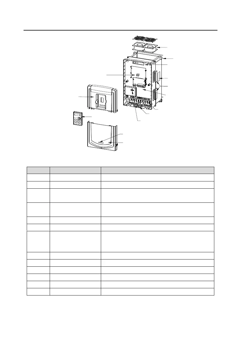
Fig 3-6 Structure diagram
Serial No.
Name
Illustration
1
Keypad interface
Connect the keypad
2
Upper cover plate
Protect the internal parts and components
3
Keypad
See Chapter 5 "Keypad operation procedures" for detailed
information
4
Cooling fan
See Chapter 9 "Routine maintenance" for detailed
information
5
Wiring interface
Connect to the control board and the drive board
6
Nameplate
See Chapter 3 "Product overview" for detailed information
7
Ventilation hole cover
plate
Optional. The ventilation hole cover plate will increase the
protection level as well as the internal temperature of the
VFD, which requiring the VFD to be used under derating.
8
Control terminals
See Chapter 4 "Installation guide" for detailed information
9
Main circuit terminals
See Chapter 4 "Installation guide" for detailed information
10
Main circuit cable inlet
Fix the main circuit cable
11
POWER light
Power indicator
12
Simple nameplate
See section 3.5 "Model code" for detailed information
13
Lower cover plate
Protect the internal parts and components

Table of Contents

Questions and Answers:

Question and Answer IconNeed help?

Do you have a question about the INVT Goodrive35 Series and is the answer not in the manual?

INVT Goodrive35 Series Specifications

General IconGeneral
BrandINVT
ModelGoodrive35 Series
CategoryController
LanguageEnglish

Related product manuals