Goodrive35 Series Closed-loop Vector Control VFD Extension card
242
A.2.6.3 Bus net connection of EC-TX-103 communication card
1. Bus communication interface
Transformation by double-shielded twisted pair copper cable is the most common way in PROFIBUS
(conform to RS-485standard).
The basic characteristics of transformation technology:
● Net topology: Linear bus, there are bus resistor in two ends.
● Transforming speed: 9.6k bit/s–12M bit/s
● Medium: Double-shielded twisted pair cables, the shield can be removed according to the
environment (EMC).
● Station number: There are 32 stations in each segment (without relays) as to 127 stations (with
relays)
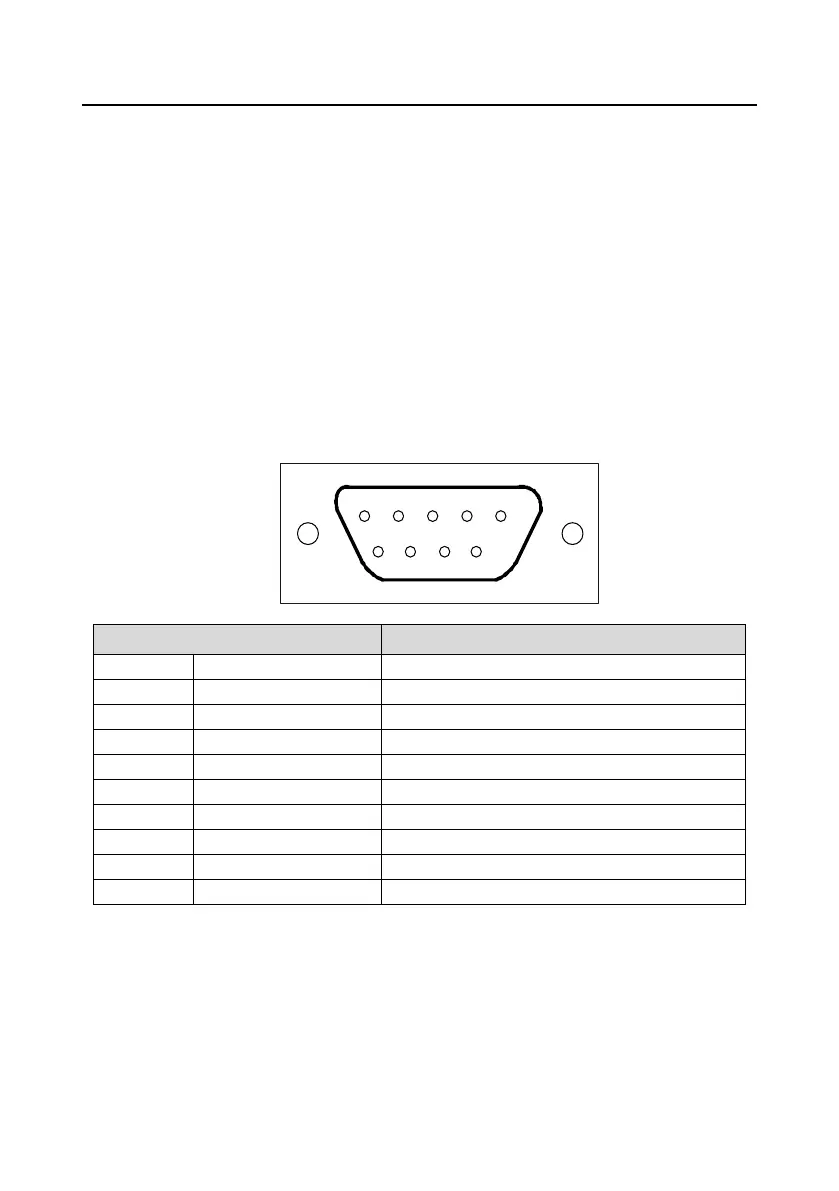
● Contact pin: 9 frames D pin, the connector contact pins are as below:
Contact pin of the connector
Positive data (twisted pair cables 1)
Isolated 5 V DC power supply
Negative data (twisted pair cables 2)
+5 V and GND_BUS are used in the fieldbus terminals. Some devices, such as light transceiver
(RS485) may get external power supply form these pins.
RTS is used in some devices to determine the sending direction. Only A-Line wires, B-Line wires and
shield layer are used in the normal application.
It is recommended to apply the standard DB9 connector of SIEMENS. If the communication baud rate
is above 187.5kbps, please follow the connection rules of SIEMENS seriously.

 Loading...