Goodrive35 Series Closed-loop Vector Control VFD Optional peripheral accessories
287
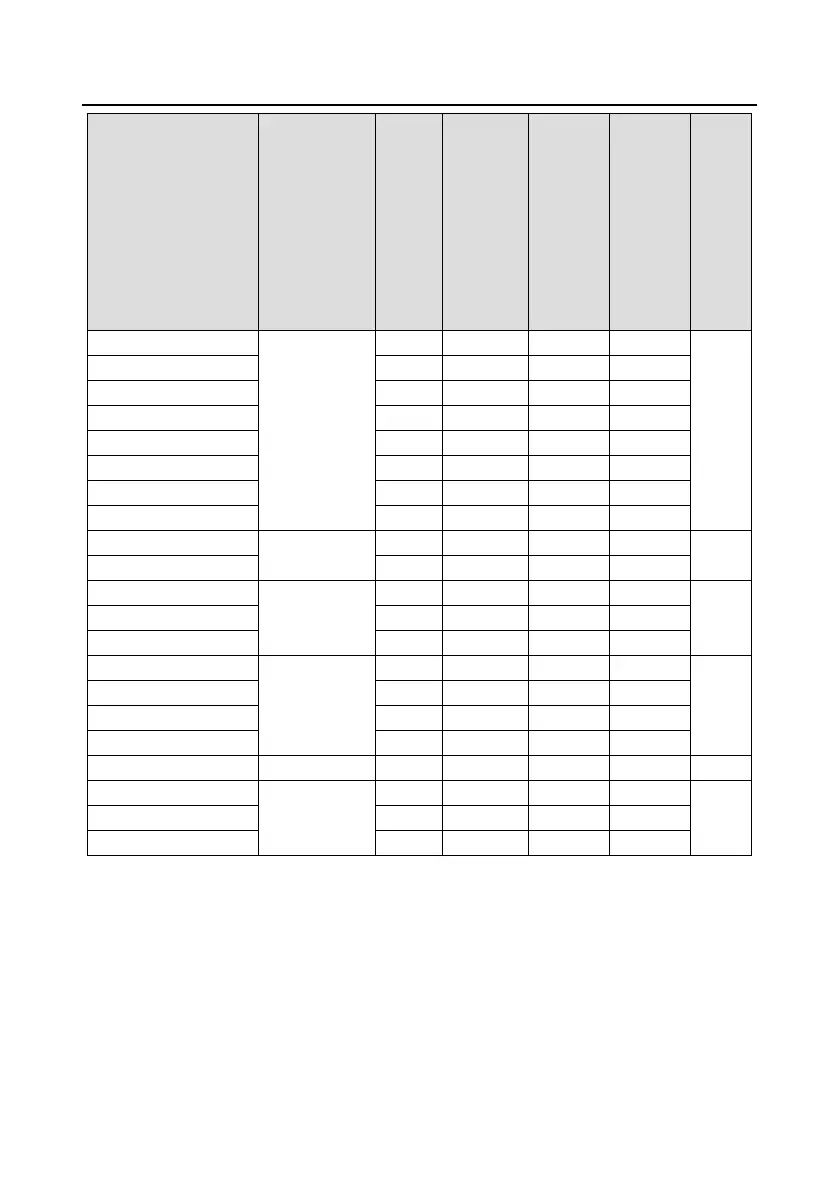
Brake
resistor
value
matched
with
100%
brake
torque
(Ω)
Dissipation
power of
brake
resistor
(kW)
(10%
brake)
Dissipated
power of
brake
resistor
(kW)
(50%
brake)
Dissipated
power of
brake
resistor
(kW)
(80%
brake)
Min
allowed
brake
resistor
(Ω)
Note:
1. Select brake resistors according to the resistance and power data provided by our company.
2. The brake resistor may increase the brake torque of the VFD. The preceding table describes the
resistance and power for 100% brake torque, 10% brake usage, 50% brake usage, and 80% brake
usage. You can select the brake system based on the actual operation conditions.
3. When using an external brake unit, set the brake voltage class of the brake unit properly by
referring to the manual of the dynamic brake unit. If the voltage class is set incorrectly, the VFD may
not run properly.

 Loading...