Goodrive35 Series Closed-loop Vector Control VFD Installation guide
25
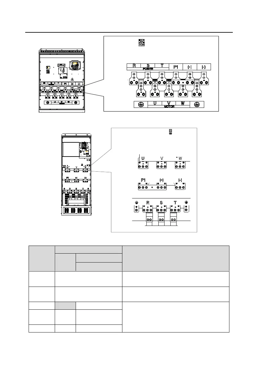
Figure 4-17 Terminals of main circuit for the VFDs of 380 V 220–315 kW and 660 V 250–350 kW
Figure 4-18 Terminals of main circuit for the VFDs of 660 V 400–630 kW
Power input of the main circuit
3-phase AC input terminals which are generally
connected with the power supply.
3-phase AC output terminals which are generally
connected with the motor.
P1 and (+) are connected with the terminals of DC
reactor.
(+) and (-) are connected with the terminals of
brake unit.
DC reactor terminal 2,
brake unit terminal 1

 Loading...