Goodrive35 Series Closed-loop Vector Control VFD Keypad operation procedures
40
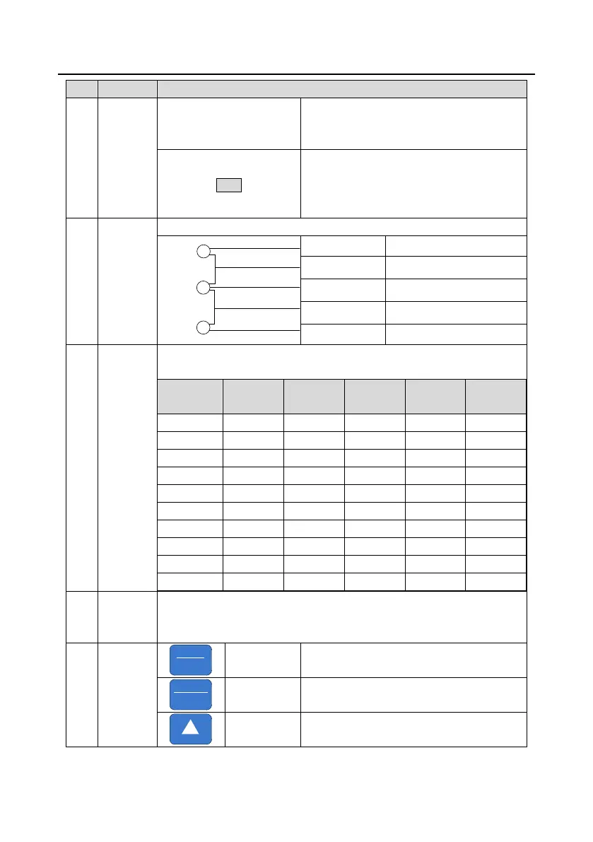
is in the terminals operation state; LED on
means the VFD is in the remote
communication control state.
LED for faults
LED on when the VFD is in the fault state; LED
off in normal state; LED blinking means the
VFD is in the pre-alarm state.
Mean the unit displayed currently
5-figure LED display displays various monitoring data and alarm code such as
set frequency and output frequency.
Displayed
word
Correspon
ding word
Displayed
word
Correspon
ding word
Displayed
word
Correspon
ding word
0 0 1 1 2 2
3 3 4 4 5 5
6 6 7 7 8 8
9 9 A A B B
C C d d E E
F F H H I I
L L N N n n
O o P P r r
S S t t U U
V v . . – -
Tuning frequency. Please refer to P08.42.
PRG
ESC
Enter or escape from the first level menu and
remove the parameter quickly
DATA
ENT
Enter the menu step-by-step
Confirm parameters
Increase data or function code progressively

 Loading...