SV-DA200 series AC servo drives Faults and solutions
‐90‐
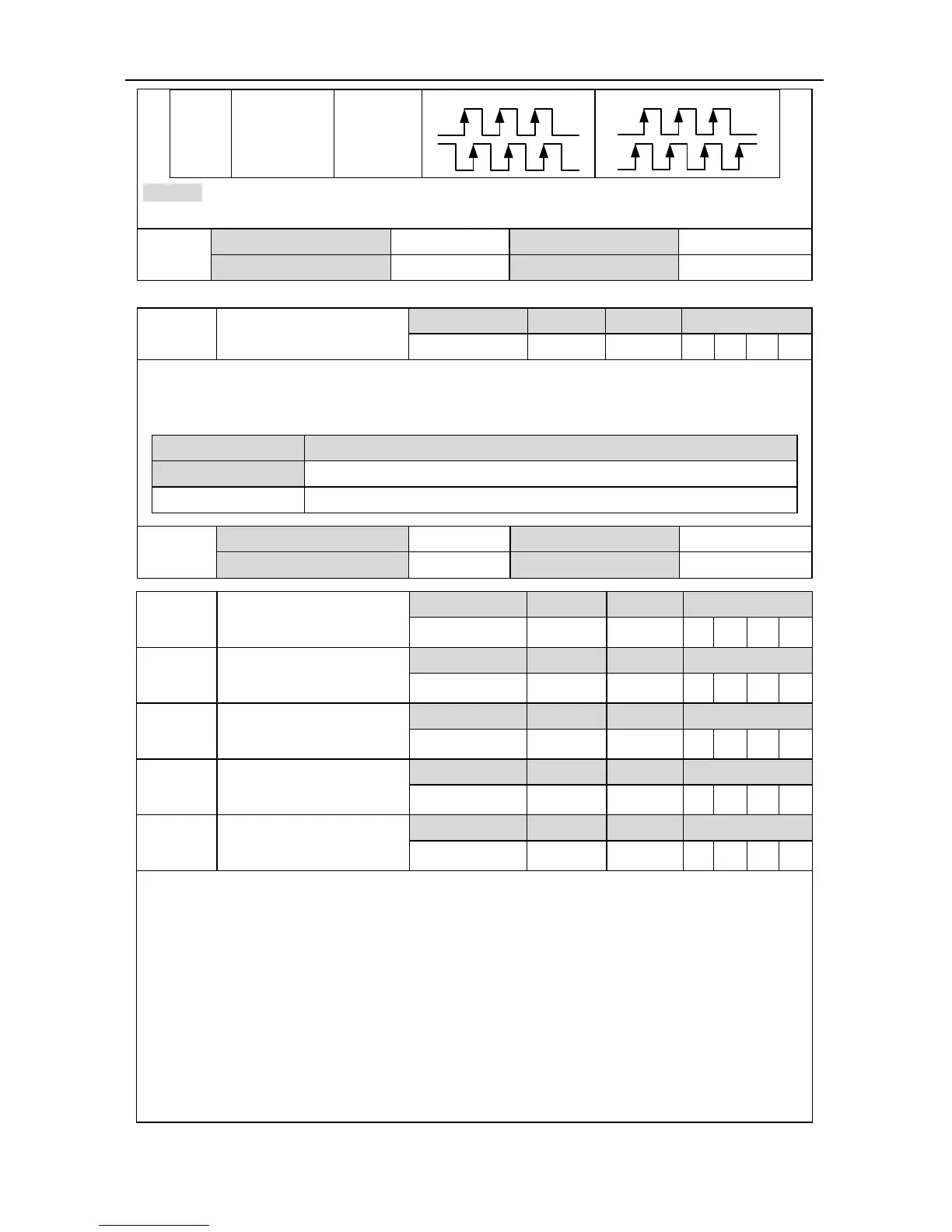
2
Quadrature
encoder
pulse mode
QEP
Remark: The pulse direction of the parameter can be reversed by P0.24
1
. Please refer to P0.24
1
for detailed information.
P0.23
1
Data size 16bit Data format DEC
Modbus address 1046,1047 CANopen address 0x2017, 0x00
P0.24
1
Reverse of pulse input
direction
Setting range Default Unit Available mode
0~1 0 - P F
By setting this parameter, the direction of the input pulse can be reversed. At this time the actual
output speed direction of the servo drive is opposite to the direction indicated by the pulse input
form in P0.23.
Setting value Pulse input
[0] Pulse input direction does not change
1 Pulse input direction is opposite to the original input direction
P0.24
1
Data size 16bit Data format DEC
Modbus address 1048,1049 CANopen address 0x2018, 0x00
P0.25
Numerator of 1
st
electronic gear ratio
Setting range Default Unit Available mode
0~(2
31
-1) 0 - P
F
P0.26
2
Denominator of the
electronic gear ratio
Setting range Default Unit Available mode
1~(2
31
-1) 10000 - P
F
P0.27
Numerator of 2
nd
electronic gear ratio
Setting range Default Unit Available mode
0~(2
31
-1) 0 - P
F
P0.28
Numerator of 3
rd
electronic gear ratio
Setting range Default Unit Available mode
0~(2
31
-1) 0 - P
F
P0.29
Numerator of 4
th
electronic gear ratio
Setting range Default Unit Available mode
0~(2
31
-1) 0 - P
F
Concept of the electronic gears: for any pulse input, the number and frequency of the pulse
actually received by the drive can be changed by multiplying a certain coefficient and this
coefficient is electronic gear ratio. It can be indicated in two parts: numerator and denominator:
Electronic gear ratio = g1/ g2;
Of which
g1: The numerator of the electronic gear ratio;
g2: The denominator of the electronic gear ratio;
 Loading...
