SV-DA200 series AC servo drives Faults and solutions
‐91‐
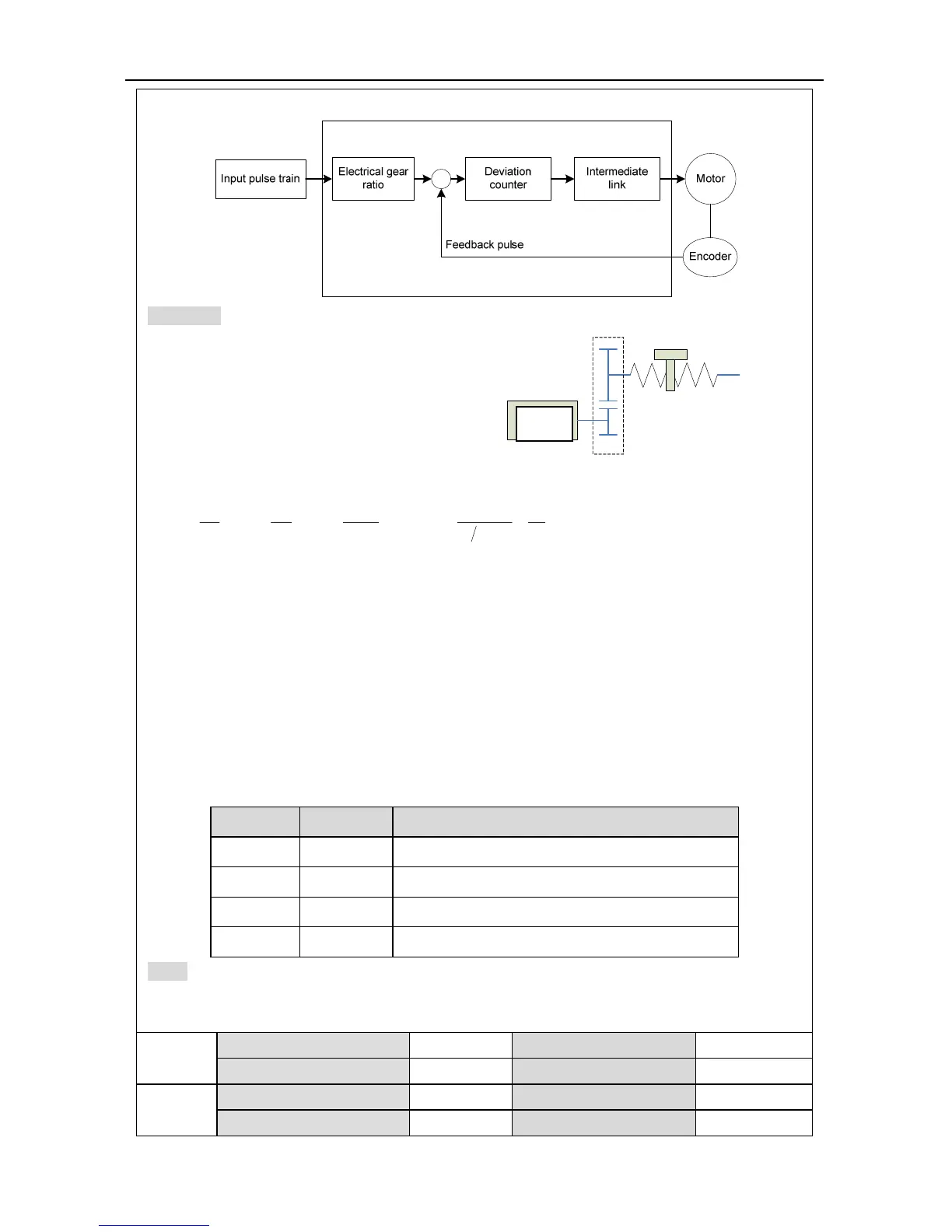
Below is the schematic diagram of the electronic gear ratio in the system:
Example: Below is a case where 1 pulse is
equivalent to a feed rate of 10μm
Mechanical specifications:
Feed of the ball screw Pb =10mm;
Reduction ratio n=3/5;
Resolution of the servo motor encoder =10000;
At this time calculate the electronic gear ratio:
3
00
1 10000 50
10 10
2(35)103
gPt Pt
gSnPb
In the formula :
0
: Feed rate corresponding to each pulse (mm/pulse);
S : Feed rate corresponding to each rotation of the motor (mm/rot).
i.e. in this example, g1=50, g2=3.
Set P0.25 to 50 and P0.26 to 3.
The servo drive has 4 groups of electric gear ratio: P0.25, P0.26, P0.27 and P0.28, P0.29 can
select to adopt which parameter group to provide the electronic gear ratio through the digital
input configured as electronic gear ratio selection function (SC1, SC2) on CN1,plug, the
corresponding relation is shown below:
SC1 SC2 Position mode/Fully-closed loop mode
0 0 Numerator of 1
st
electronic gear ratio
1 0 Numerator of 2
nd
electronic gear ratio
0 1 Numerator of 3
rd
electronic gear ratio
1 1 Numerator of 4
th
electronic gear ratio
Note:
1. The parameters are valid when P0.22
1
is 0.
2. Switch the electronic gear ratio via digital quantity (SC1, SC2), P4.10 must be set to 0.
P0.25
Data size 32bit Data format DEC
Modbus address 1050,1051 CANopen address 0x2019, 0x00
P0.26
2
Data size 32bit Data format DEC
Modbus address 1052,1053 CANopen address 0x201A, 0x00
伺服电机
n
Servo
motor
 Loading...
