SV-DA200 series AC servo drives Faults and solutions
‐95‐
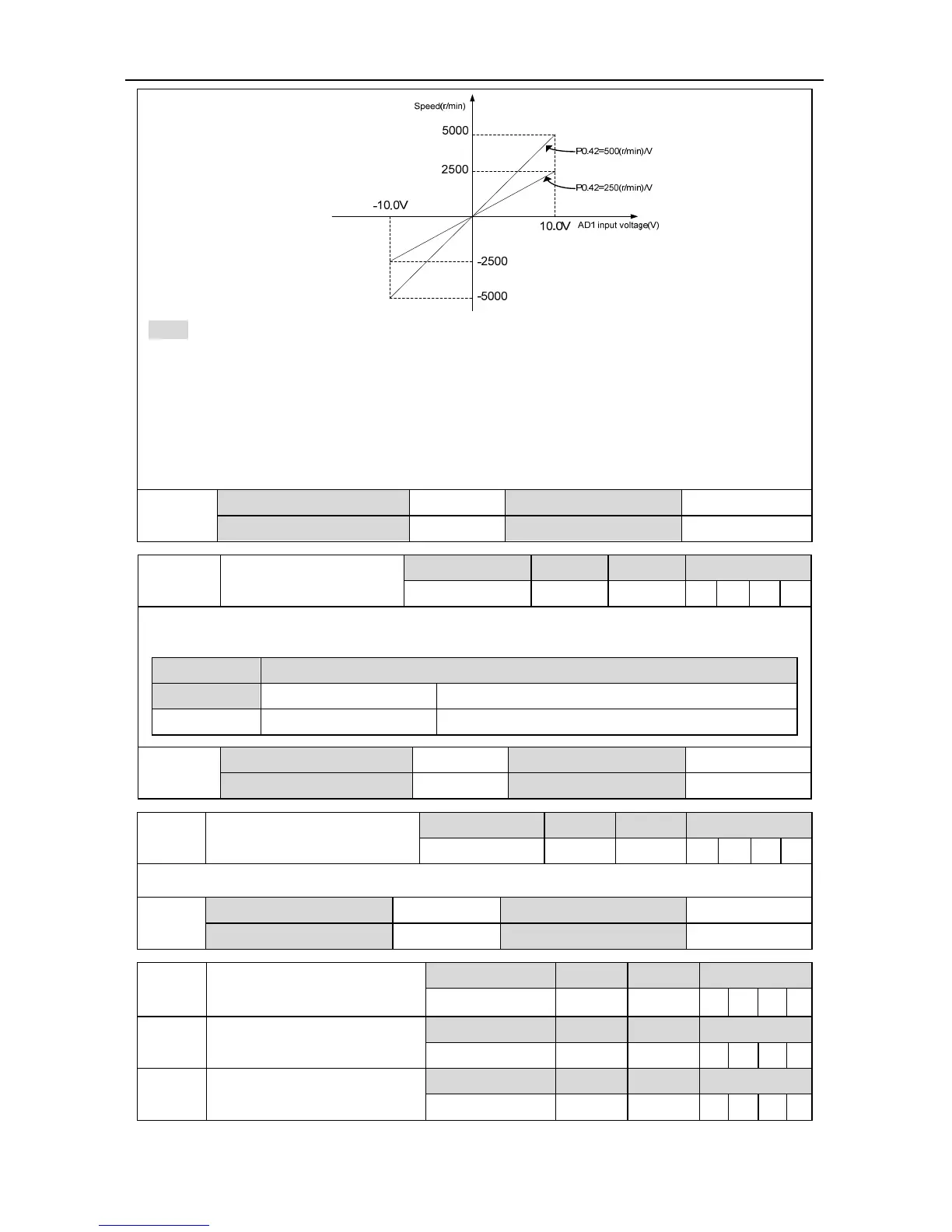
Note:
1. The default is the input signal from analog input terminal 1 of CN1 (AD1, GND and pin “1”,“5”).
2. This parameter is valid when the setting value of P0.40 is “1”.
3. Set the parameter correctly after confirming the motor operation, if the setting is too large, the
motor speed will fluctuate a lot.
4. The voltage above -10~10V cannot be applied between AD1 and GND, otherwise, the drive
may be damaged.
P0.42
Data size 32bit Data format DEC
Modbus address 1084,1085 CANopen address 0x202A, 0x00
P0.43 Analog input 1 reverse
Setting range Default Unit Available mode
0~1 0 - S
Suppose the analog input 1 function selection is speed command.
This parameter is used to set the voltage polarity of the analog speed command.
Setting value Motor direction
[0] Positive polarity [+voltage]→[Positive],[- voltage]→[Negative]
1 Negative polarity [+voltage]→[Negative],[- voltage]→[Positive]
P0.43
Data size 16bit Data format DEC
Modbus address 1086,1087 CANopen address 0x202B, 0x00
P0.45 Dead zone of analog input 1
Setting range Default Unit Available mode
0.000~3.000 0.000 V S
If the absolute value of analog input 1 voltage is in this range, the corresponding command value is 0.
P0.45
Data 16bit Data format DEC
Modbus address 1090,1091 CANopen address 0x202D, 0x00
P0.46 Internal speed 1/Speed limit 1
Setting range Default Unit Available mode
-20000~20000 100 r/min S T
P0.47 Internal speed 2/Speed limit 2
Setting range Default Unit Available mode
-20000~20000 0 r/min S T
P0.48 Internal speed 3/Speed limit 3
Setting range Default Unit Available mode
-20000~20000 0 r/min S T
 Loading...
