SV-DA200 series AC servo drives Faults and solutions
‐126‐
2. The input voltage should be no more than 10V, otherwise damage may occur to the drive.
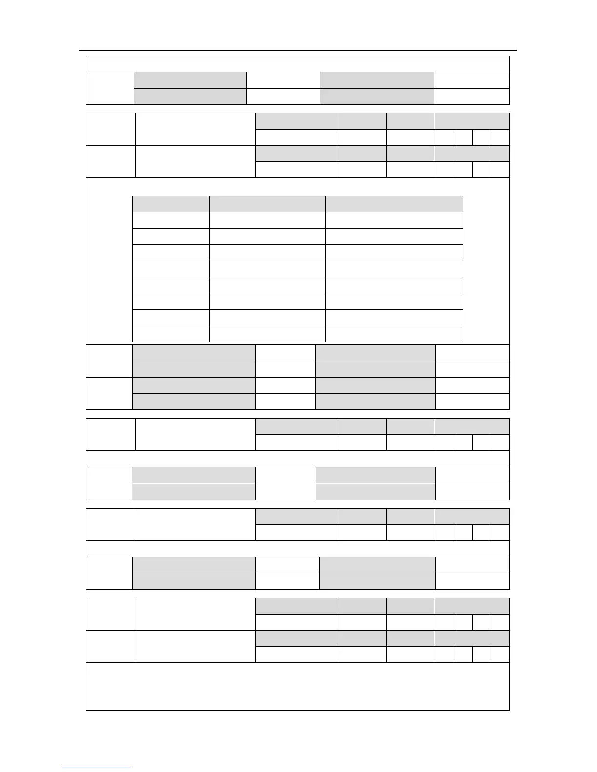
P3.25
Data size 32bit Data format DEC
Modbus address 1650,1651 CANopen address 0x2319,0x00
P3.26
1
Function selection of
analog input 1
Setting range Default Unit Available mode
0~7 0 - P S T F
P3.27
1
Function selection of
analog input 2
Setting range Default Unit Available mode
0~7 3 - P S T F
Select the analog input channel function via this parameter
Setting value Definition Unit
[0] Invalid -
1 Speed limit r/min
2 Forward torque limit 0.1%
3 Speed command r/min
4 Torque command 0.1%
5 Speed compensation r/min
6 Torque compensation 0.1%
7 Negative torque limit 0.1%
P3.26
1
Data size 16bit Data format DEC
Modbus address 1652, 1653 CANopen address 0x231A, 0x00
P3.27
1
Data size 16bit Data format DEC
Modbus address 1654, 1655 CANopen address 0x231B, 0x00
P3.28
Analog speed
compensation gain
Setting range Default Unit Available mode
0.0~100.0 0.0 % P S T F
Set the analog speed compensation gain via this parameter.
P3.28
Data size 16bit Data format DEC
Modbus address 1656, 1657 CANopen address 0x231C, 0x00
P3.29
Analog torque
compensation gain
Setting range Default Unit Available mode
0.0~100.0 0.0 % P S T F
Set the analog torque compensation gain via this parameter.
P3.29
Data size 16bit Data format DEC
Modbus address 1658, 1659 CANopen address 0x231D, 0x00
P3.30
1
analog output 1 selection
Setting range Default Unit Available mode
0~19 0 - P S T F
P3.32
1
analog output 2 selection
Setting range Default Unit Available mode
0~19 0 - P S T F
This group of parameters is used to select the monitoring parameters to be outputted in analog
form.
 Loading...
