SV-DA200 series AC servo drives Faults and solutions
‐127‐
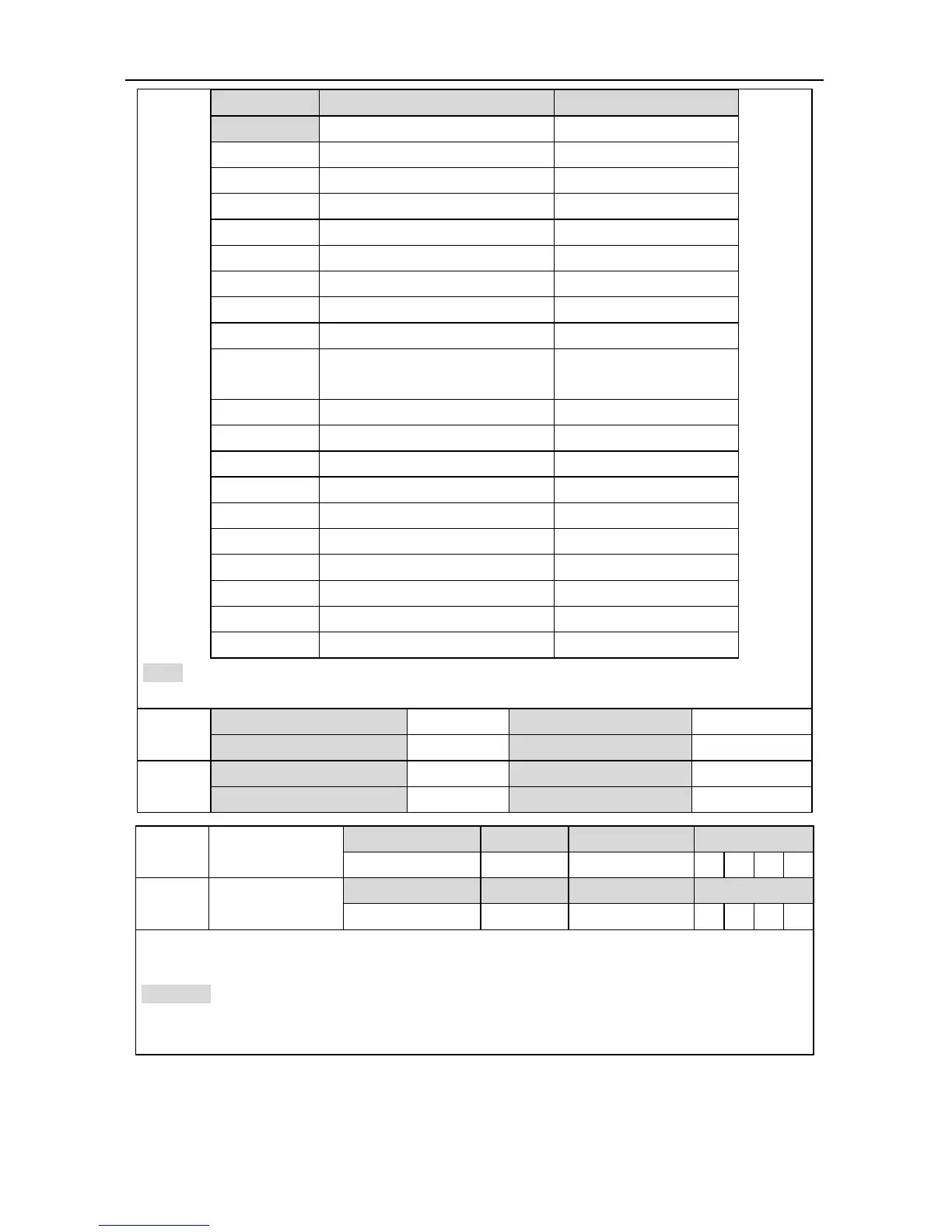
Setting value Definition Unit
[0] Invalid -
1 Motor speed r/min
2 Speed of position command r/min
3 Internal position command pulse(Encoder unit)
4 Speed command r/min
5 Torque command 0.1%
6 Torque feedback 0.1%
7 Command position deviation reference unit
8 Encoder position deviation pulse(Encoder unit)
9 Fully-closed loop position deviation
pulse(Linear encoder
unit)
10 Hybrid control deviation reference unit
11 DC voltage of main circuit V
12 Positive torque limit 0.1%
13 Negative torque limit 0.1%
14 Speed limit value r/min
15 Inertia ratio %
16 Analog speed command* V
17 Analog torque command* V
18 Analog input 3* V
19 Drive temperature ℃
Note: When P3.31, P3.33 is set to 1000, the analog speed command, analog torque command
and analog input 3 outputs the voltage value inputted from the analog input terminal at any time.
P3.30
1
Data size 16bit Data format DEC
Modbus address 1660, 1661 CANopen address 0x231E, 0x00
P3.32
1
Data size 16bit Data format DEC
Modbus address 1664, 1665 CANopen address 0x2320, 0x00
P3.31
Voltage gain of
analog output 1
Setting range Default Unit Available mode
0~214748364 0 [P3.30 Unit]/V P S T F
P3.33
Voltage gain of
analog output 2
Setting range Default Unit Available mode
0~214748364 0 [P3.32 Unit]/V P S T F
These parameters are used to set the gain of analog output. The detailed unit is relative to P3.30
and P3.32.
Example: Suppose the actual speed is outputted from the AO1 terminal, 10V corresponds to a
speed of 3000r/min and 0V corresponds to 0. Then set P3.30=1, P3.31=300, the relation between
the actual speed reference and output voltage is shown as below:
 Loading...
