SV-DA200 series AC servo drives Faults and solutions
‐133‐
7 Negative-direction torque limit 0.1%/V
Note:
*
1
If P3.70 is 2 and P0.09 is 0 or 4, the analog input 3 corresponds to the positive torque limit
internally and P0.62~P0.65, P3.23~P3.25 correspond to the negative torque limit internally.
*
2
If P3.70 is 3, P0.42~P0.45, P3.20~P3.22 are invalid.
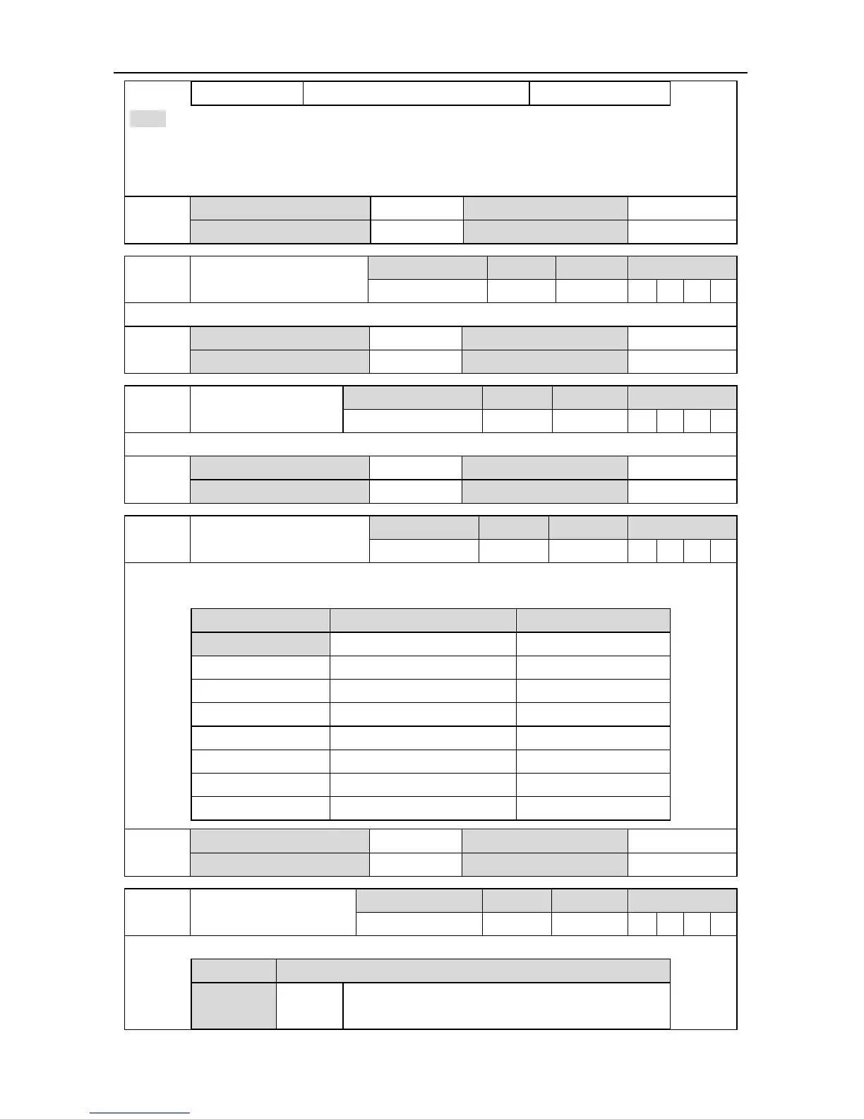
P3.70
1
Data size 16bit Data format DEC
Modbus address 1740,1741 CANopen address 0x2346,0x00
P3.71
Zero offset of analog input
3
Setting range Default Unit Available mode
-10.000~10.000 0.000 V P S T F
The zero offset voltage of analog input 3.
P3.71
Data size 32bit Data format DEC
Modbus address 1742,1743 CANopen address 0x2347,0x00
P3.72
Dead zone of analog
input 3
Setting range Default Unit Available mode
0.000~3.000 0.000 V P S T F
Dead zone range of analog input 3.
P3.72
Data size 16bit Data format DEC
Modbus address 1744,1745 CANopen address 0x2348,0x00
P3.73 Gain of analog input 3
Setting range Default Unit Available mode
0~2000 300 - P S T F
This parameter is used to set the gain of analog input 3. The units correspond to different function
of P3.70 are listed below:
P3.70 Setting value Definition P3.73 unit
[0] Invalid -
1 Speed limit (r/min)/V
2 Torque limit 0.1%/V
3 Speed command (r/min)/V
4 Torque command 0.1%/V
5 Speed compensation (r/min)/V
6 Torque compensation 0.1%/V
7 Negative torque limit 0.1%/V
P3.73
Data size 32bit Data format DEC
Modbus address 1746,1747 CANopen address 0x2349,0x00
P3.74 Analog input 3 reverse
Setting range Default Unit Available mode
0~1 0 - P S T F
This parameter is used to set the voltage polarity of analog input 3.
Setting value Detection result
[0]
Positive
polarity
[+voltage] → [positive],[- voltage] → [negative]

 Loading...