SV-DA200 series AC servo drives Faults and solutions
‐139‐
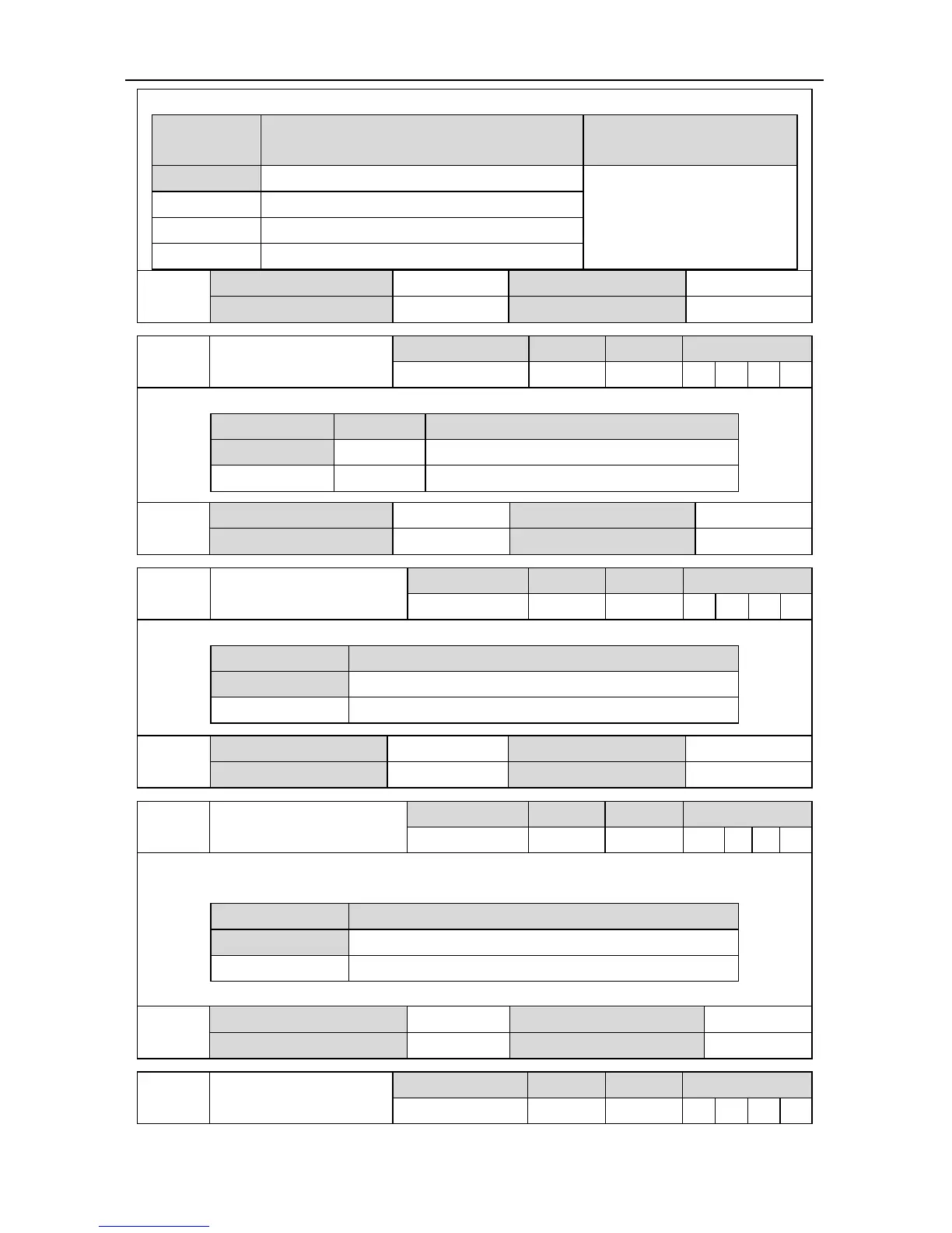
If P4.10 is 1, this parameter can be used to set the switching command of electronic gear ratio.
Setting value Molecule of actual electronic gear ratio
Denominator of actual
electronic gear ratio
[0] Molecule of 1
st
electronic gear ratio (P0.25)
Denominator of electronic
gear ratio (P0.26)
1 Molecule of 2
nd
electronic gear ratio (P0.27)
2 Molecule of 3
rd
electronic gear ratio (P0.28)
3 Molecule of 4
th
electronic gear ratio (P0.29)
P4.17*
Data size 16bit Data format DEC
Modbus address 1834,1835 CANopen address 0x2411,0x00
P4.18*
Inertia ratio switching
command
Setting range Default Unit Available mode
0~1 0 - P S T F
If P4.10 is 1, this parameter can be used to set the inertia ratio switching command.
Setting value Function Actual inertia ratio
[0] Disabled The first inertia ratio (P1.01)
1 Enabled The second inertia ratio (P1.02)
P4.18*
Data size 16bit Data format DEC
Modbus address 1836,1837 CANopen address 0x2412,0x00
P4.19*
Zero speed clamp
command
Setting range Default Unit Available mode
0~1 0 - S T
If P4.10 is 1, this parameter can be used to set the zero speed clamp command.
Setting value Function
[0] Disabled
1 Enabled
P4.19*
Data size 16bit Data format DEC
Modbus address 1838,1839 CANopen address 0x2413,0x00
P4.20* Retention pulse clearing
Setting range Default Unit Available mode
0~1 0 - P F
If P4.10 is 1, this parameter can be used to set the retention pulse clearing. The detailed mode is
determined by P3.45 and after clearing, R0.04 is 0.
Setting value Function
[0] Disabled
1 Enabled
P4.20*
Data size 16bit Data format DEC
Modbus address 1840,1841 CANopen address 0x2414,0x00
P4.21*
Torque limit switching
command
Setting range Default Unit Available mode
0~1 0 - P S T F
 Loading...
