222 Chapter 13: System Operation TempScan / MultiScan User's Manual
Additional Operation
Trigger Latency
Each trigger source has an associated latency. This latency is the time between the actual Trigger
(trigger start event) and its recognition by the TempScan/1100 or MultiScan/1200 unit.
The following latency times are simplistic representations of the time between when the Trigger is
detected and when the Trigger has been processed. The hardware latency times, and the Interrupt
Service Routine (ISR) times to process other tasks during the trigger event but before its detection, are
not accounted for. In other words, these times may be offset as much as the hardware latency times, in
addition to the process time taken by the longest uninterrupted ISR.
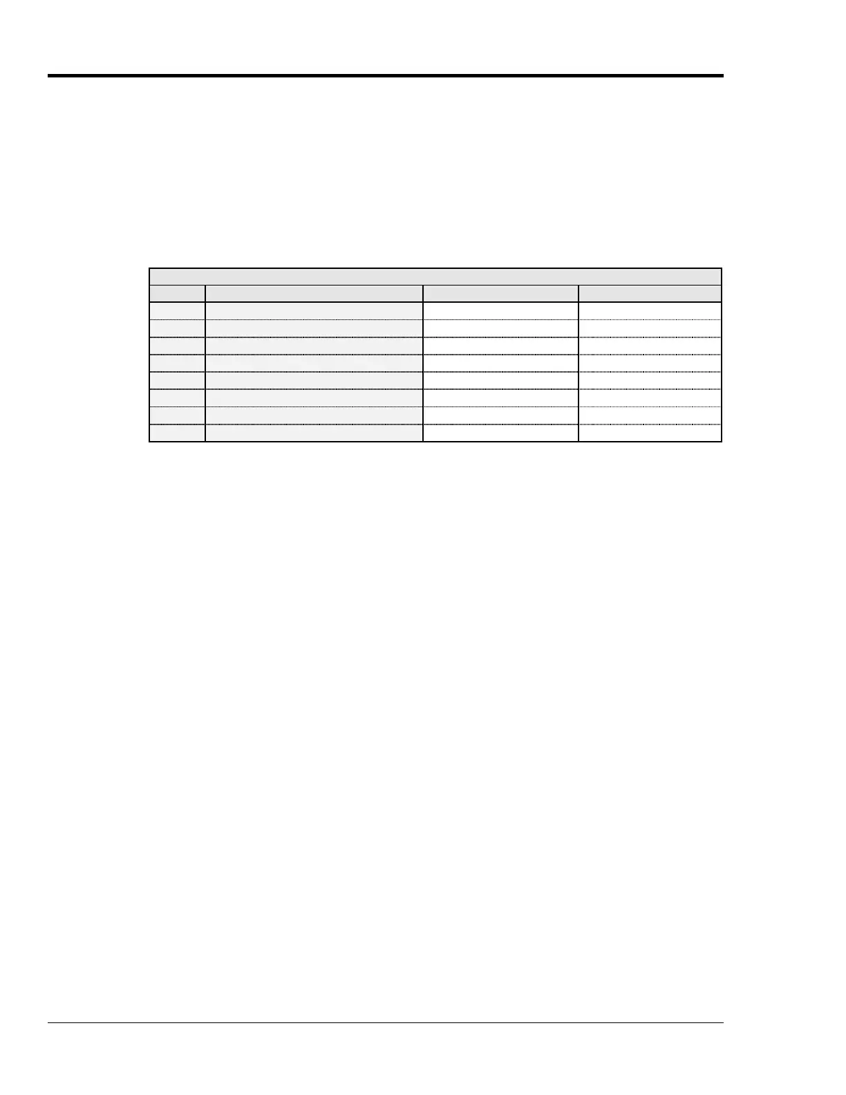
Trigger Source & Latency
Type(s) Trigger Source Trigger Latency (Average) Observed Variation
1
@ character 2.255 ms 620.00 µs
2
GET (IEEE only) 645.6 µs 3.10 µs
3
TALK (IEEE only) 780.53 µs 12.00 µs
4,5
Selected Temperature Channel (Level) (See Note below) (See Note below)
6,7
External TTL (Rising or Falling) 610.95 µs 2.10 µs
8
Count (Post-Trigger) 45.9 µs 28.5 µs
9,10
Alarm (See Note below) (See Note below)
11
Absolute Time 44.5 µs 27.0 µs
Note:
(1) When using a channel level or alarm as the trigger source, the trigger latency is dependent
on the number of channels. (2) With the TempScan/1100 unit, the maximum trigger latency is
the minimum scan time interval (as dictated by the maximum possible frequency) allowable
by the current configuration. (3) With the MultiScan/1200 unit, the maximum trigger latency
is the greater of the following time values: The programmed scan time interval, or the
minimum scan time interval (as dictated by the maximum possible frequency) allowable by
the current configuration.
Real-Time Clock
The TempScan/1100 or MultiScan/1200 contains a battery-backed-up internal real-time clock which is
programmable when set and read. Factory set according to Eastern Standard Time (U.S.), the real-time
clock runs in military time. Although setting the real-time clock time via the Set Real-Time Clock (
S
)
command, and setting the Trigger (trigger start event) and Stop (trigger stop event) times via the
Program Trigger Times (
P
) command, are done at a resolution of only 0.1 second (tenths of a second),
the real-time clock actually operates at a resolution of 0.001 second (milliseconds). This millisecond
resolution is evident in the Time/Date stamping of channel data output which is retrieved from the
High/Low/Last (HLL) Registers or the Acquisition Buffer.
For more information on setting the real-time clock, see command Set Real-Time Clock (
S) in the
chapter API Command Reference. For more information on Time/Date stamping and data formats, see
section Stamping Configuration and section Data Format Configuration in the chapter System
Configuration.
 Loading...