34 Chapter 4: Exp/11A Expansion Unit TempScan / MultiScan User's Manual
Three (3) LED indicators on the front panel of the Exp/11A display the status of the expansion unit:
• SCAN: ON when the master unit is storing a expansion channel scan in its internal buffer.
• ERROR: ON when an error has occurred, OFF when no error condition exists. For more
information, see command Query Error Status (
E?).
• POWER: ON when power is applied to the unit and the power switch on the back panel is in the
ON position (depressed). OFF if power is not present.
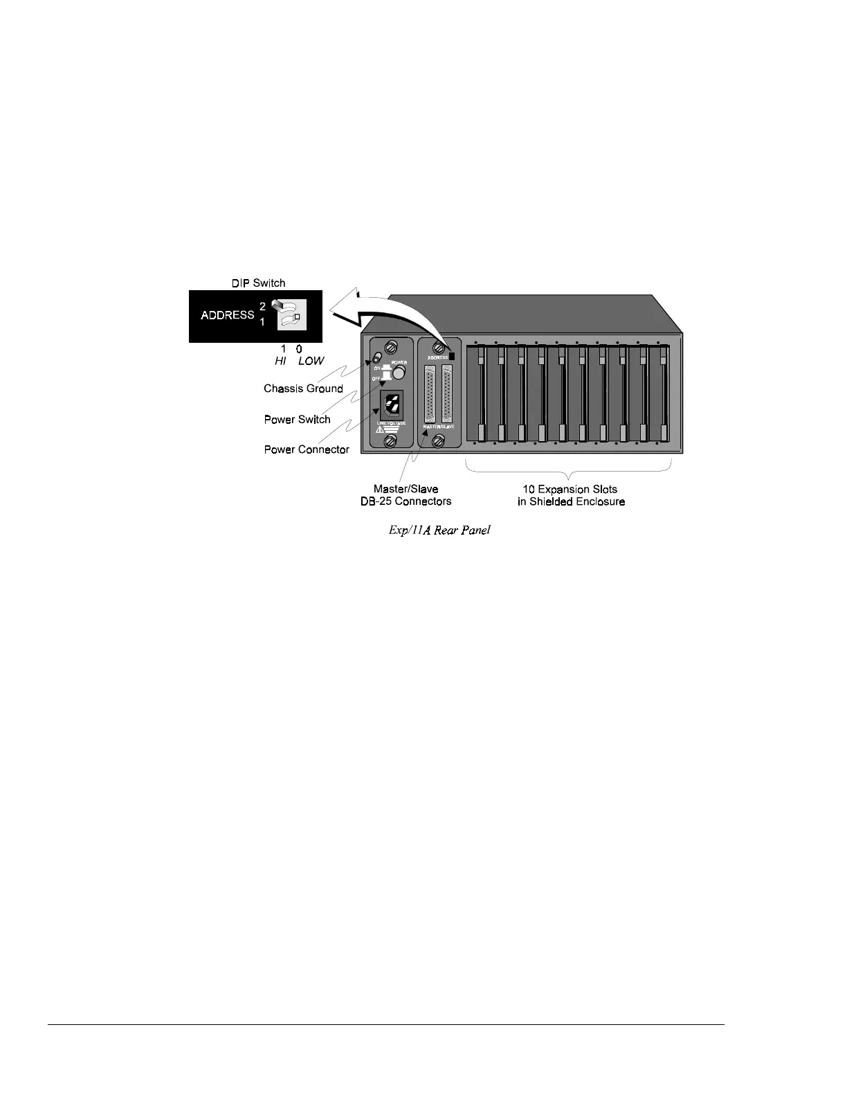
Rear Panel Switches & Connectors
Two (2) switches, three (3) connectors, one (1) grounding nut, and ten (10) input card slots on the rear
panel of the Exp/11A provide power, slave addressing, master/slave connections, a single point
grounding node, and scanning card expansion.
• Power Switch: Used to turn power to the Exp/11A ON and OFF. When the switch is in the
depressed position the power is ON. When in the extended position, the power is OFF.
• DIP Switch: Used for selecting the Exp/11A slave address ID.
• Power Connector: Provides power for the unit. Internally configurable for either 105-125 or 210-
250 VAC, 50/60Hz, plus fuse circuit breaker.
• Master/Slave Connector: Two DB25 master/slave ports provide one connection to a
TempScan/1100, MultiScan/1200, Exp/10A or Exp/11A unit, and one connection to another
Exp/10A or Exp/11A expansion unit.
• Grounding Screw: An external single-point grounding node has been supplied for (but not limited
to) thermocouple shield termination.
• Shielded Enclosure: For the TempScan/1100: Accepts any combination of TempTC/32B,
TempV/32B, and/or TempRTD/16B scanning cards. For the MultiScan/1200: Accepts any
combination of MTC/24 and/or MHV/24 scanning cards. Note that the TempScan/1100 and
MultiScan/1200 scanning cards must not be mixed within the same system.
 Loading...