167YLS-K
Directory of figures
Figure 1 Safety features ............................................................................................................ 24
Figure 2 Functional principle of the high power fiber laser..................................... 29
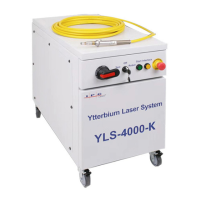
Figure 3 Overview of the laser using YLS-3000-K as example ................................ 30
Figure 4 Operating elements .................................................................................................. 31
Figure 5 Interfaces and connections ................................................................................... 32
Figure 6 Fiber connector with accessories....................................................................... 32
Figure 7 Overview: fiber connectors................................................................................... 33
Figure 8 Main components...................................................................................................... 34
Figure 9 Electrical mounting plate YLS-3000-K............................................................. 35
Figure 10 Shock monitoring...................................................................................................... 36
Figure 11 Tip monitoring............................................................................................................ 37
Figure 12 Threads for eye bolts............................................................................................... 38
Figure 13 Removing the upper cover.................................................................................... 39
Figure 14 Tensile load on the eye bolt.................................................................................. 40
Figure 15 Suspension angle during crane transport ...................................................... 40
Figure 16 Caster with fixing device........................................................................................ 41
Figure 17 Transport with pallet............................................................................................... 42
Figure 18 Removing covers ....................................................................................................... 48
Figure 19 Connection of the supply voltage ....................................................................... 49
Figure 20 Additional earthing connection .......................................................................... 49
Figure 21 Connecting the external interfaces.................................................................... 50
Figure 22 Fiber connectors with and without protective cap .................................... 51
Figure 23 Water connections.................................................................................................... 54
Figure 24 Control tab.................................................................................................................... 62
Figure 25 Program sequence example.................................................................................. 69
Figure 26 Setup LaserNet welcome window...................................................................... 71
Figure 27 Setup LaserNet - Destination location.............................................................. 71
Figure 28 Setup LaserNet - Selecting the Start menu folder ....................................... 72
Figure 29 Setup LaserNet - Additional tasks...................................................................... 72
Figure 30 Setup LaserNet - Installing the software......................................................... 73
Figure 31 Setup LaserNet - Finishing the installation.................................................... 73
Figure 32 Internet Protocol Properties ................................................................................ 74
Figure 33 LaserNet no connection.......................................................................................... 75
Figure 34 IP Configuration dialog window......................................................................... 75
Figure 35 LaserNet status tab (example) ............................................................................ 77
Directory of figures