Quick Reference
Confirm settings
After completing the value setting or selecting a menu item, pushing the knob
acts like pressing [Enter] key to confirm the operation.
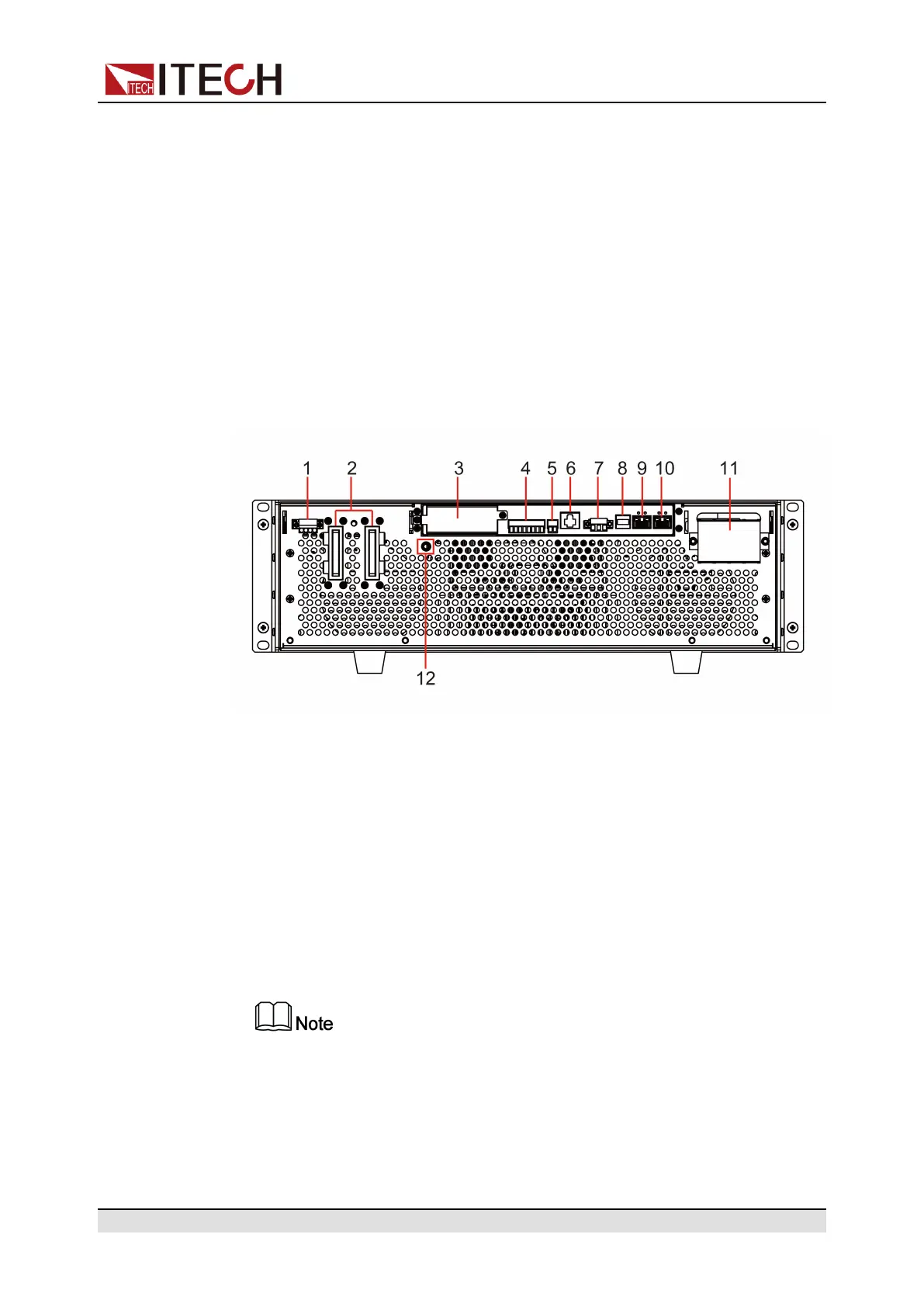
1.5 Rear Panel Introduction
The rear panel of the 3U model of the IT6000B series Regenerative Power Sys-
tem (after removing the protective cover) is shown below. The rear panel of the
6U model is the same as the 3U model.
3U Models
1. Sense terminals (Vs+, Vs-)
2. DC output terminals of the power supply (or DC input terminals of the load)
3. Interface for optional accessories IT-E166 and IT-E167 (For details, see 1.9
Options Introduction)
4. Digital I/O interface: P-IO
5. CAN communication interface
6. LAN communication interface
7. External control interface CTRL
This interface is used for the parallel connection between the master (with
operation panel) and the slaves (without operation panel). Connect the in-
terface on the rear panel of each unit to be connected in parallel, and the
master can offer synchronous control over the power-on/off of the slaves.
8. USB communication interface
Copyright © Itech Electronic Co., Ltd.
8