Basic Operation
2. Based on the above formula conversion relationship, calculate the M (slope
coefficient) and b (offset) values of the voltage setting value.
For example: When the instrument voltage input range is 0-100V, the user
needs a 0-10V analog signal to control the setting value of 0-100V. Then, M
is: 100–0/10–0=10, and b is: 0–0=0
3. Press the composite keys [Shift]+[P-set] (System) on the front panel to en-
ter the system menu.
4. Use knob or Up/Down key to select Ext-Program and press [Enter].
5. Set the Ext-Program→On / Off to On to turn on the analog function.
6. Use Up/Down key or knob to select the menu item CV, and set the M and b
values in CV mode.
7. Input low-level voltage 1V in Pin 9, and input high-level voltage 3V in Pin 10.
Switch the existing mode to CV mode. For detailed mode definition, refer to
the description of analog quantity interface.
8. Input 0-10V voltage in Pin 8, and control the setting value of the input voltage
of this instrument.
For example, when the input voltage of Pin 8 is 1V, the setting value of the
input voltage of this instrument is 10V; when the input voltage of Pin 8 is 5V,
the setting value of the input voltage of this instrument is 50V. The corre-
sponding relationship meets the calculation relationship of y=Mx+b.
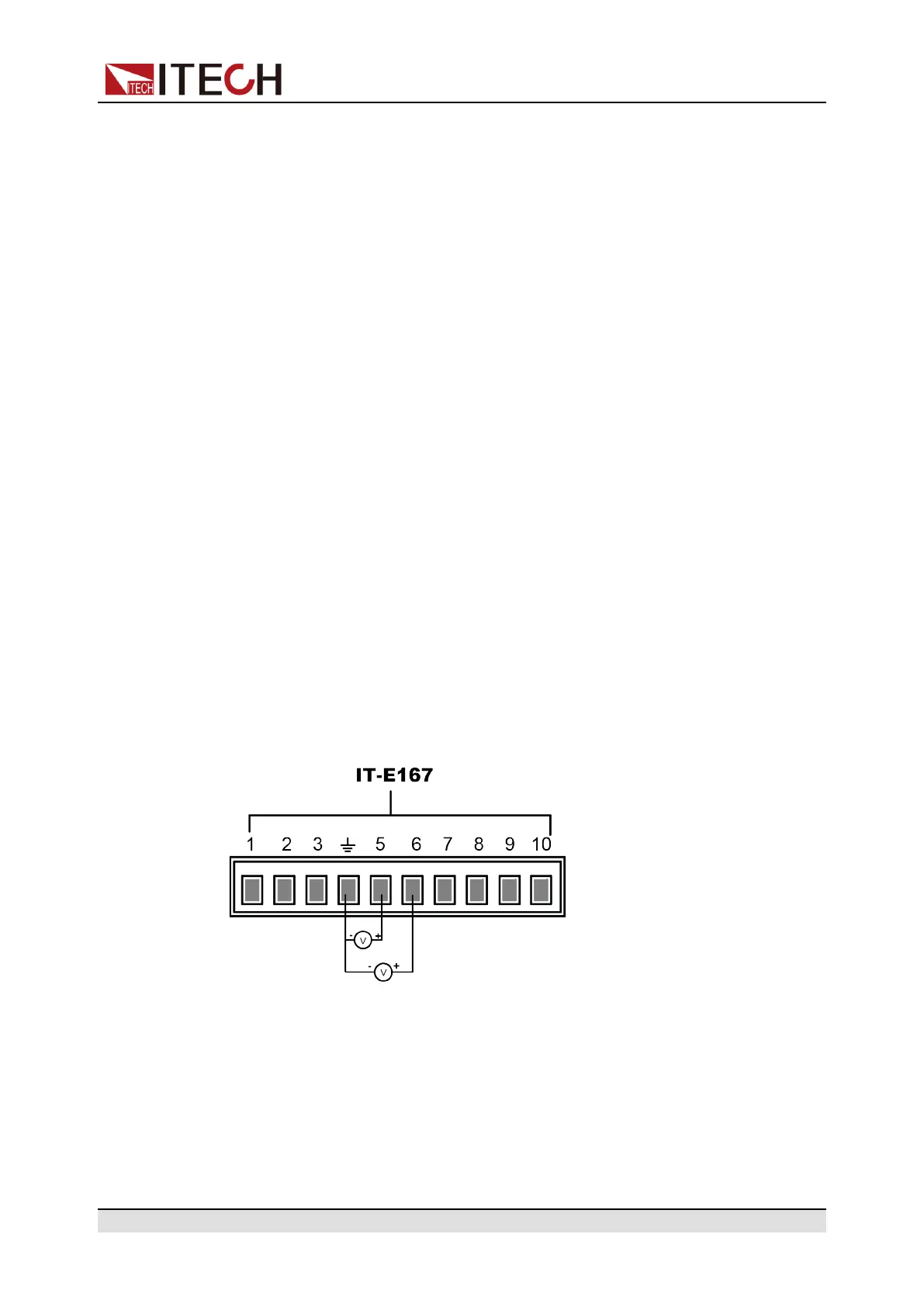
Voltage Monitoring and Current Monitoring
The analog interface can monitor the existing input voltage and input current.
Connect a digital voltmeter between Pin 5 and Pin 6 of the analog interface and
ground wire 4. The connection method is as shown below. The voltage reading
from 0 to 10V corresponds to the zero to full-scale voltage/current setting of the
instrument. The connection diagram is as shown below.
6.14 Restored to Factory Setting (System Reset)
This menu item is used to restore some parameter settings to factory setting
values.
The procedures to set the menu item are as follows.
Copyright © Itech Electronic Co., Ltd.
215