Inspection and Installation
Specification for Test Cables
The number of test cables shipped with the instruments varies with the model of
the instrument. For details, see2.2 Verifying the Shipment. For models that do
not come standard with test cables, please select optional red and black test ca-
bles for individual sales based on the maximum current value. For specifications
of test cables and maximum current values, refer to A.1 Appendix→Specifica-
tions of Red and Black Test Lines.
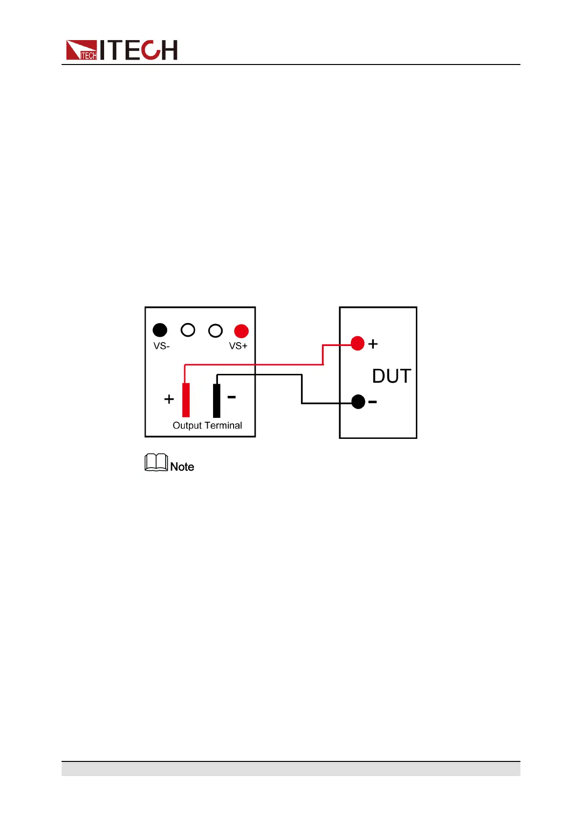
Connecting the DUT (Local Measurement)
The instrument supports two kinds of wiring methods with the DUT: local meas-
urement and remote measurement (SENSE). The default test mode is local
measurement.
The connection diagram and steps of local measurement are as follows:
For Regenerative Power System, the input terminals in Load mode are the
same terminals as the output terminals in Source mode. Therefore, this man-
ual uses Source mode as an example to describe how to connect to the
DUT.
1. Confirm that the power switch is in the OFF position and verify that there is
no dangerous voltage on the connection terminals.
2. Remove the output terminals cover of the power system.
3. Loosen the screws of the output terminals and connect the red and black
test cables to the output terminals. Re-tighten the screws.
When maximum current that one test cable can withstand fails to meet the
rated current, use multiple pieces of red and black test cables. For example,
the maximum current is 1,200A, then 4 pieces of 360A red and black cables
are required.
4. Thread the red and black test cables through the output terminals cover of
the power system and install the cover.
5. (Optional) According to the actual situation of DUT, connect the grounding
terminal on the rear panel of the instrument to the DUT to ensure the safe
grounding.
Copyright © Itech Electronic Co., Ltd.
34