File Version: 3.4 / JAKA Zu Series Hardware User Manual
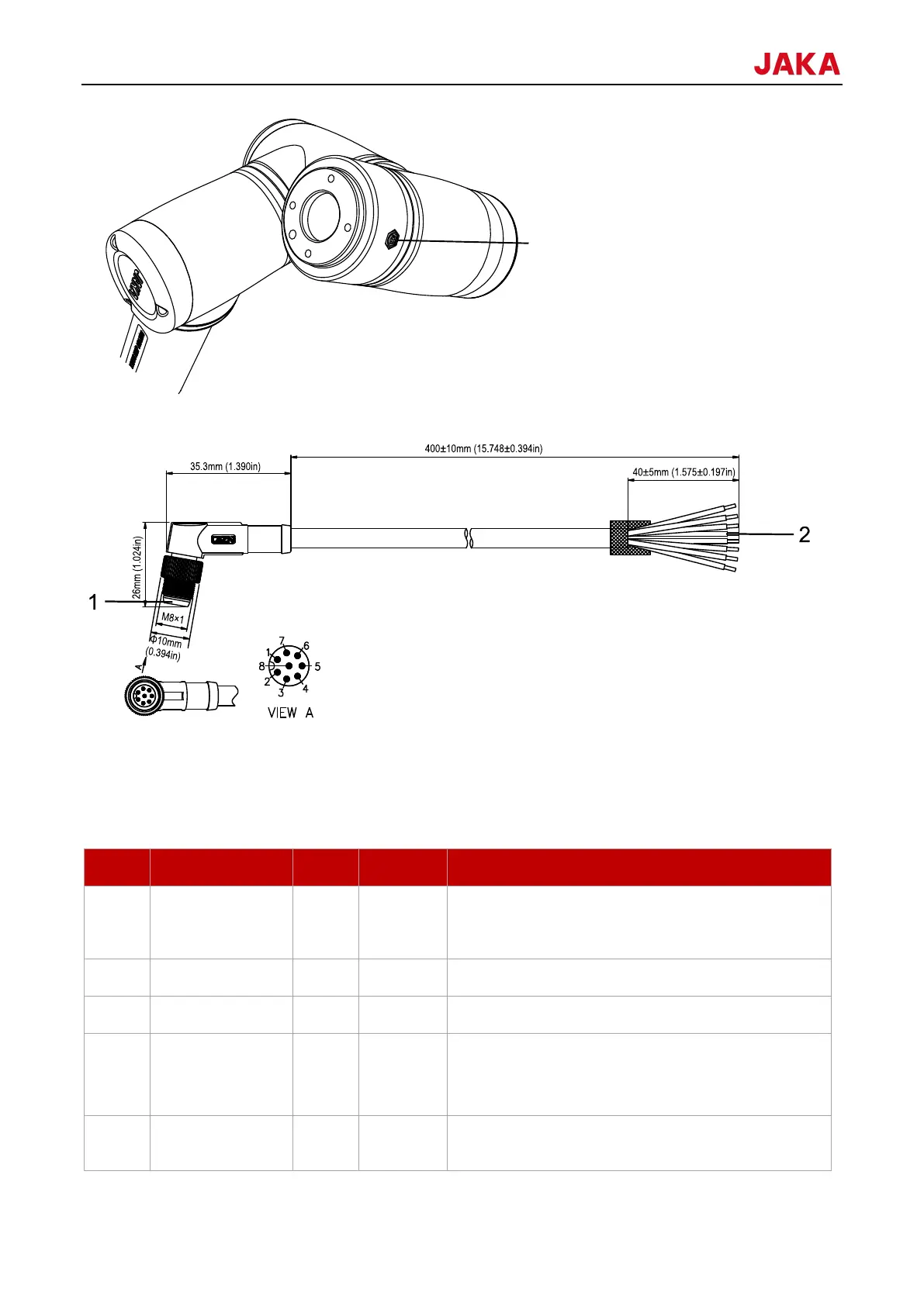
The definition and specifications of the TIO cable are as follows.
1. Connect the robot flange
2. Connect the end-effector
8.1.3.1
The definition table of the TIO V3.0 interfaces is as follows:
Positive electrode, 24V/12V (switchable); configurable
for enabling or disabling; continuous current capacity
1A; peak output current up to 2A.
Digital input 1: configurable to be PNP or NPN input
Digital input 2: configurable to be PNP or NPN input
Digital output 1: configurable to be PNP, NPN, or push-
pull output; current output capability ≤1A
Multiplexed as RS481 communication A+
Digital output 2: configurable to be PNP, NPN, or push-
pull output; current output capacity ≤1A
 Loading...