8.1.3.2
1.
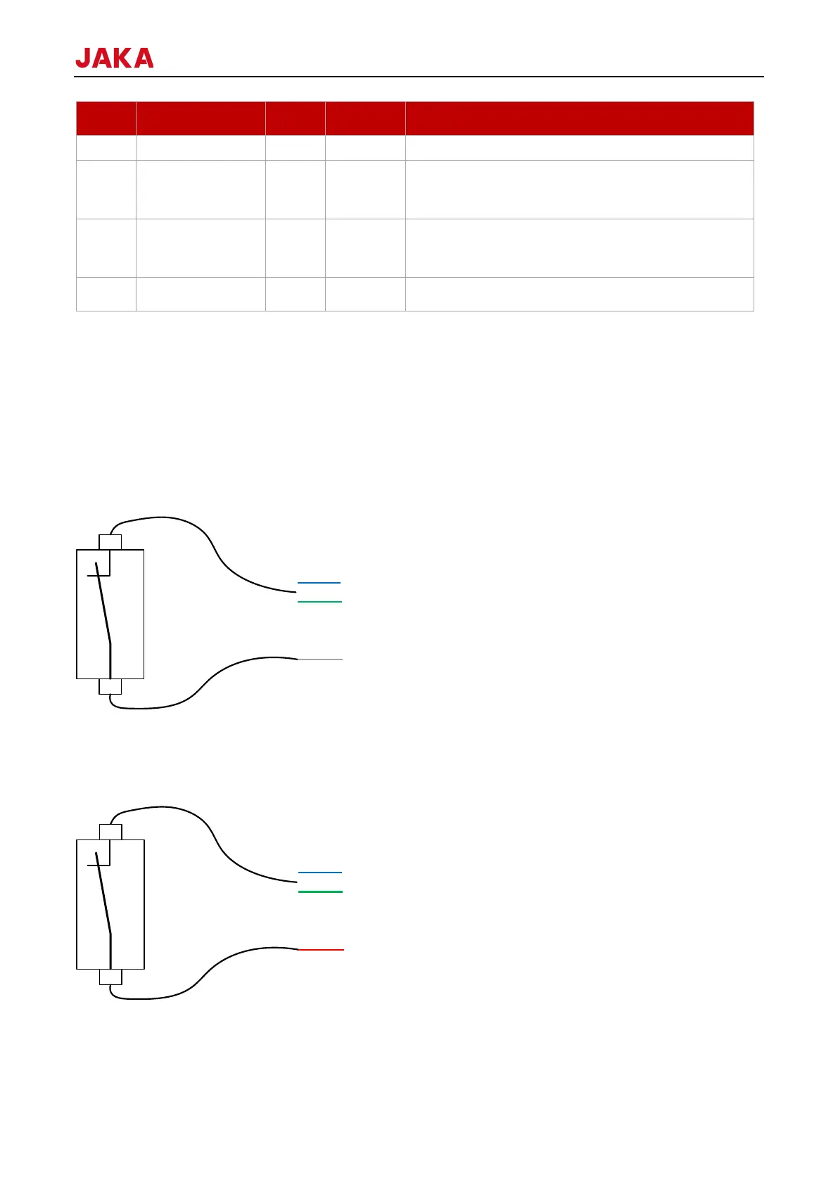
TIO supports 2 DI digital input interfaces, compatible with NPN and PNP types. It can be configured in the App.
For the details of operation, see 1.5 JAKA Zu App Software User Manual.
When the DI input is configured as NPN type:
The dry contact input (switch-type input) is connected to GND of TIO (gray wire) at one end, and to the digital
input (blue or green wire) at the other end.
When the DI input is configured as PNP type:
The dry contact input (switch-type input) is connected to GND of TIO (gray wire) at one end, and to the digital
input (blue or green wire) at the other end.
The connection method of NPN and PNP type digital input devices: V+ is connected to 24V of TIO (red wire),
0V is connected to GND of TIO (gray wire), and the signal wire is connected to the digital input of TIO (blue or
 Loading...