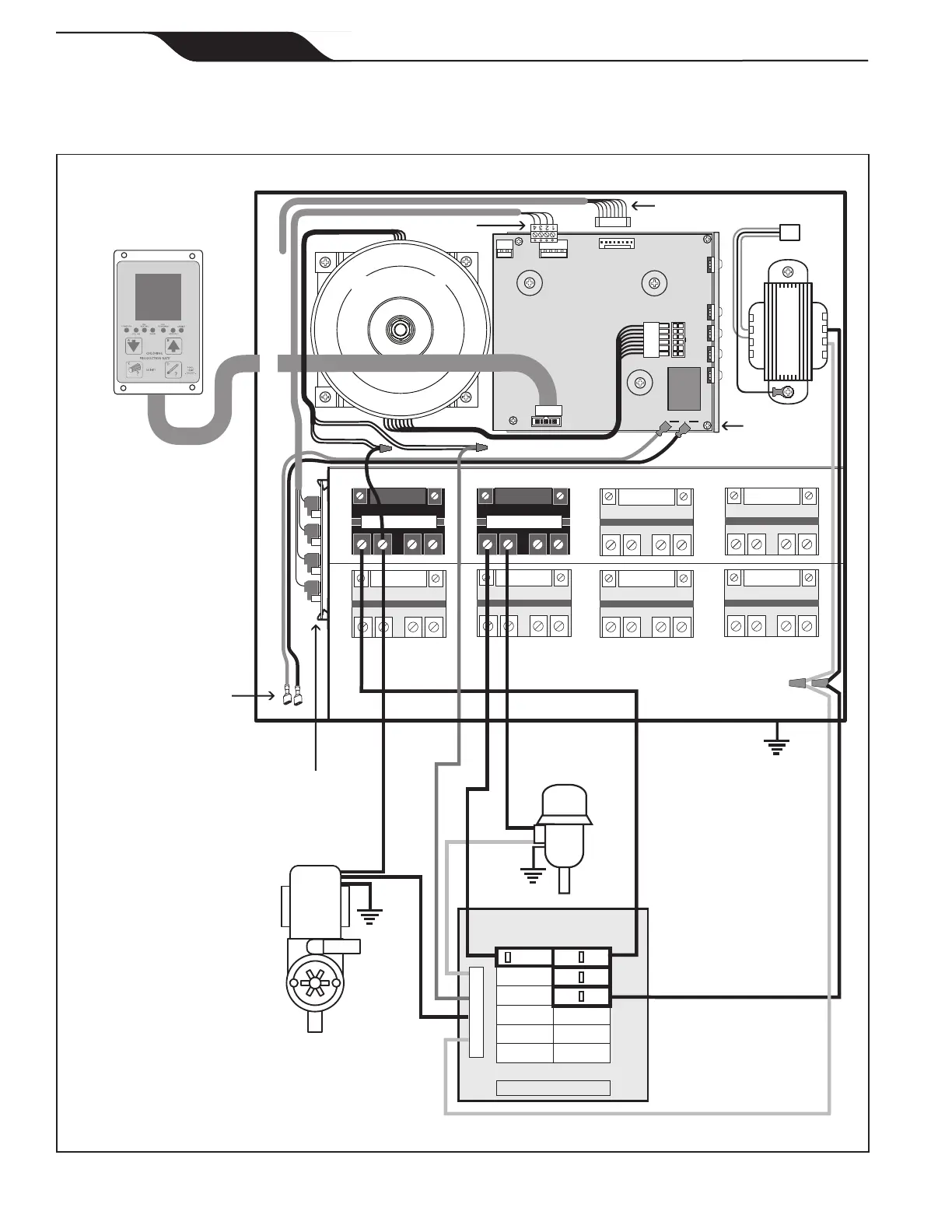
Figure 2b. Wiring Diagram for the PureLink
TM
System with a 120 VAC Filter Pump
Filter Pump Relay
Aux. 3 Relay
Line 1
Wire Nut to
120 VAC Power
Breakers
Ground
Neutral
Blower
(120 VAC)
Filter Pump
(120 VAC)
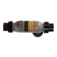
To Electrolytic
Cell
Multiplex Board
(J1 through J4)
J1J2J3J4
Load 1
Factory wired to Multiplex Board
To AquaLink
®
24VAC
120VAC
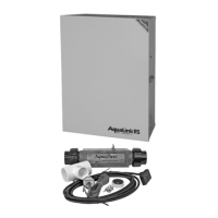
AQUALINK RS
POWER TRANSFORMER
J10 J8
CHLORINE GENERATOR
POWER INTERFACE
J13
J12
J11
Flow, Salinity, Temp Sensors
GR
Y
BK
R
HEAT SINK
L - BRACKET
BLK/RED
BLK
BLK/WHT
BLK/YEL
CHLORINE GENERATOR
USER INTERFACE
Low voltage raceway (do not run high voltage in this compartment)
PRIMARY
SECONDARY
CHLORINE GENERATOR
TRANSFORMER
Page 10
ENGLISH
Page 10
ENGLISH
Jandy
®
AquaPure
®
/PureLink™ Power Center and Cell Kit
|
Installation and Operation Manual