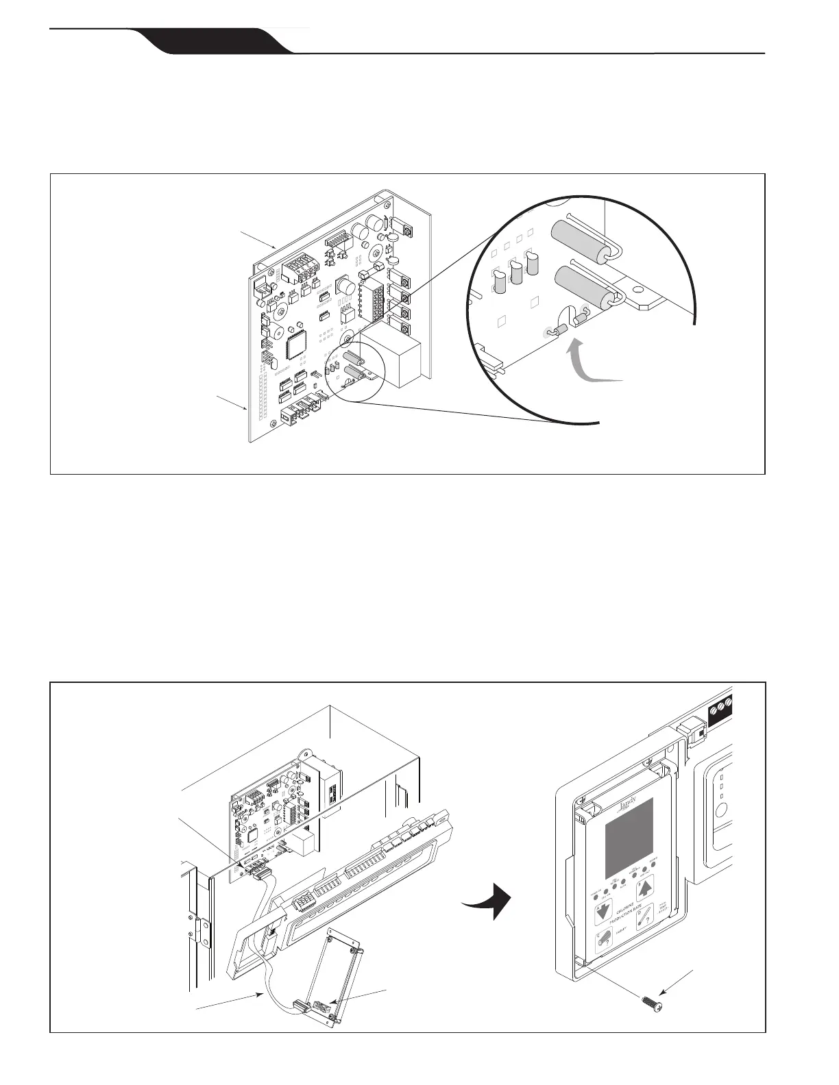
3.5 Model Conguration
The chlorine generator Power Interface Board (PIB) is congured as a 1400 model by factory default.
However, the Power Interface Board can be congured as a 700 model.
To congure the board as a 700 model, use cutting pliers to cut the JL1 jumper as shown in Figure 9.
Figure 10. Installation of the User Interface
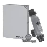
3.6 Installation of the Chlorine Generator User Interface on an AquaLink
®
RS or PDA Bezel
1. On the chlorine generator User Interface Board (UIB), connect one end of the ribbon cable to the 16-
pin J1 connector as shown in Figure 10.
2. Connect the other end of the ribbon cable to the 16-pin J1 connector on the Power Interface Board
(PIB).
3. Attach the chlorine generator User Interface Board (UIB) to the bezel using the four (4) screws
provided.
Figure 9. Chlorine Generator Power Interface Board (PIB)
J1 Connector,
Chlorine Generator
Power Interface
Board
Heat Sink
L-Bracket
Bezel Assembly
AquaLink RS Daughter Card
Mounting Area
Self-Tapping
Screw (2)
Screws (4)
Ribbon Cable
J1 Connector,
User Interface
4 3 2 1
Cut JL1 Jumper to
configure board as
Model AP700
Chlorine Generator Power
Interface Board
(PIB)
Heat Sink
L-Bracket
Page 16
ENGLISH
Page 16
ENGLISH
Jandy
®
AquaPure
®
/PureLink™ Power Center and Cell Kit
|
Installation and Operation Manual